
Apparatus and method for producing an improved laser beam

A technology of laser beams and optical components, used in lasers, laser welding equipment, laser parts and other directions, can solve the problems of small beam area, non-uniform power distribution, insufficient processing rate, etc., to improve surface quality, improve power distribution, The effect of improving the surface quality

Inactive Publication Date: 2004-05-12
UNIV OF TENNESSEE RES FOUND
View PDF1 Cites 0 Cited by
  • Summary
  • Abstract
  • Description
  • Claims
  • Application Information

AI Technical Summary

Problems solved by technology

Prior art laser beam processing equipment suffers from insufficient processing rates, resulting in part in small beam areas, non-uniform power distribution, and circular beam shapes

Method used


Image

  • Apparatus and method for producing an improved laser beam
  • Apparatus and method for producing an improved laser beam
  • Apparatus and method for producing an improved laser beam

Examples


Embodiment Construction

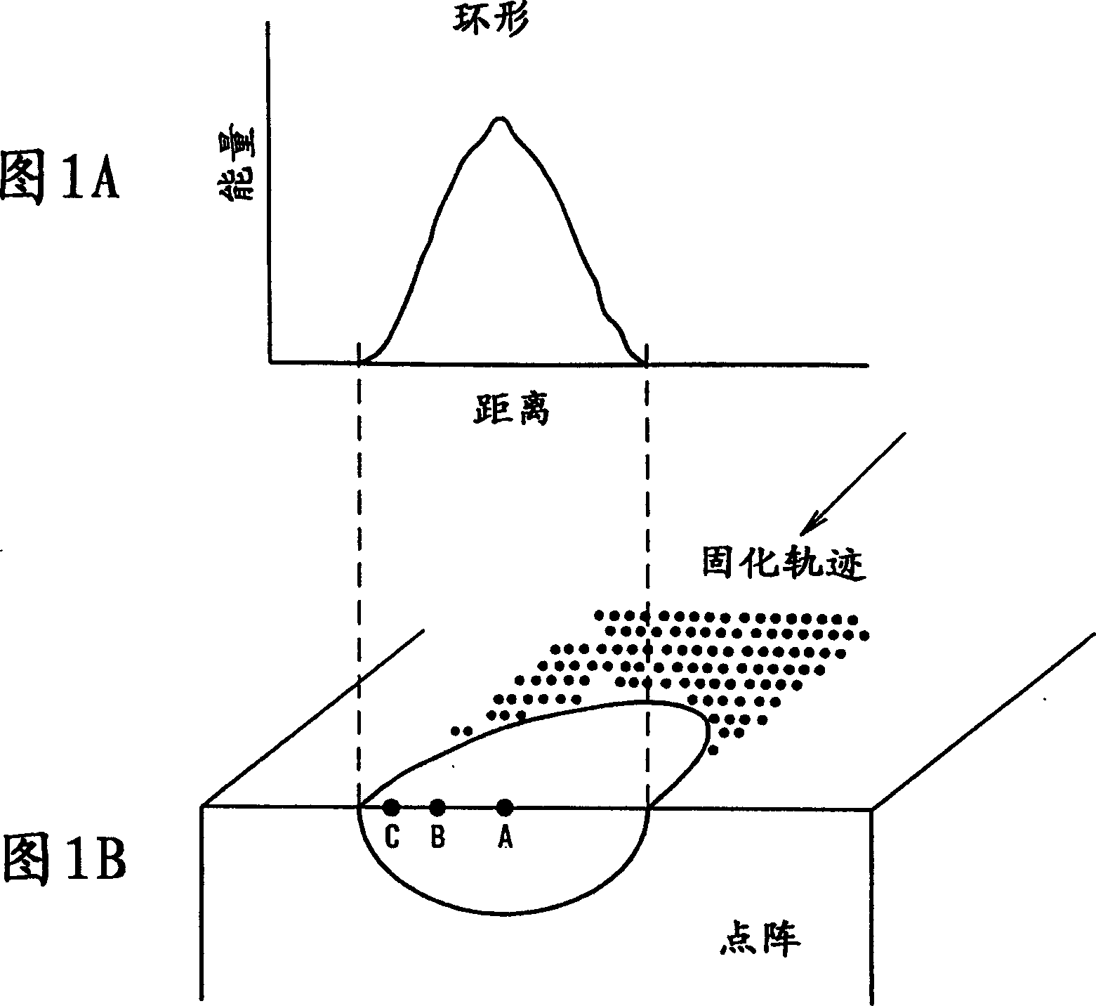
[0030] In a preferred embodiment, as attached Figure 2C As shown, the laser beam of the present invention has a rectangular cross-section 20 with a width dimension 22 and a length dimension 24 . In preferred embodiments, the width dimension of said bundle is at least 8 times the length dimension of said bundle. The ratio of the width dimension to the length dimension measured at the position of half the maximum intensity is hereinafter referred to as the "aspect ratio".

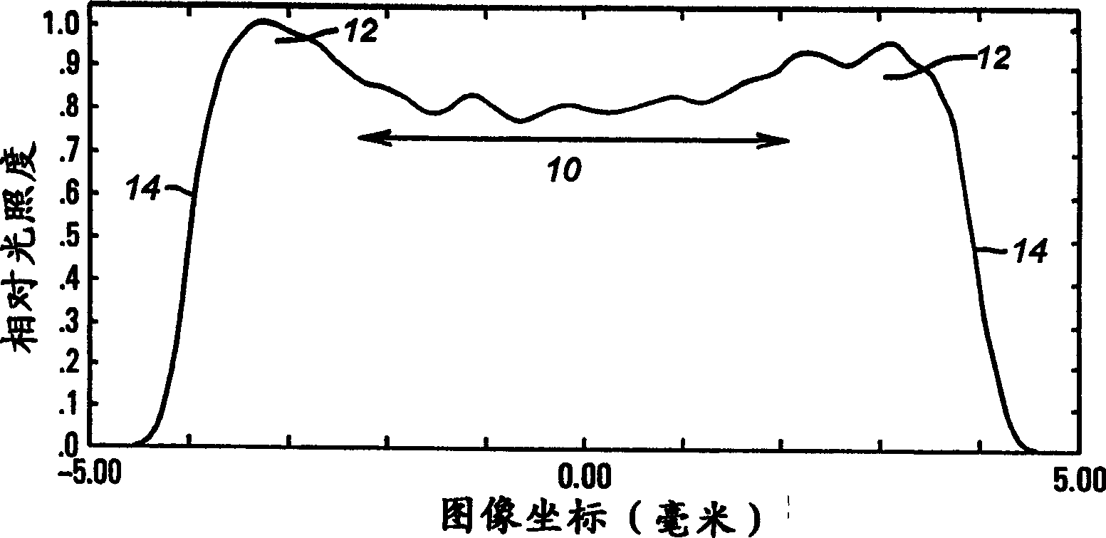
[0031] as attached Figure 2A As shown in , the laser beam of the present invention includes such a power distribution on the width dimension, that is, the power distribution is substantially constant in the central region 10, increases in the outer region 12, and substantially steps in the end regions 14 of its width dimension. function way down. The ratio of the intensity or magnitude of the power distribution in the outer zone to the intensity or magnitude in the central zone is greater than or equal t...


PUM

PropertyMeasurementUnit
Length dimensionaaaaaaaaaa

Abstract

This invention relates to an improved laser beam useful in material surface processing and an apparatus for producing the improved laser beam. The improved laser beam of the present invention comprises a power distribution that is more intense at the outer regions than in the central region. The invention includes an apparatus comprising a power spherical and cylindrical optical elements aligned to focus and / or shape a laser beam into a novel profile useful in material surface processing. The invention further includes a method of using this apparatus to focus and / or shape a laser beam for producing Laser Induced Surface Improvements, hereinafter referred to as 'LISI'.

Description

technical field [0001] The present invention relates to an improved laser beam useful in the surface treatment of materials and to an apparatus for generating the improved laser beam. The improved laser beam of the present invention includes a higher intensity power distribution in the outer zone than in the central zone. The present invention includes an apparatus comprising optical elements for focusing and / or shaping a laser beam into a novel cross-section that facilitates surface treatment of materials. Both the laser beam and the device of the present invention facilitate laser-induced surface improvement, hereinafter "LISI". Background technique [0002] Laser beams have been used to treat and / or machine workpieces, such as metal workpieces. Prior art equipment for surface treatment of materials using a laser beam includes a laser beam delivery system and a motion system for moving the workpiece relative to the laser beam. The result of the treatment of the workpiec...

Claims


Application Information

Patent Timeline
IPC IPC(8): B23K26/00B23K26/06B23K26/073G02B13/00G02B27/09H01S3/00
CPCB23K26/0639B23K26/06B23K26/0626B23K26/0665G02B27/0911B23K26/0066B23K26/0648G02B27/0966G02B27/09B23K26/064B23K26/354H01S3/101
Inventor 约翰·A·霍普金斯弗雷德里克·A·施瓦茨玛丽·H·迈凯瑟曼·D·迈凯纳雷德·B·达霍特约翰·B·拜布尔
Owner UNIV OF TENNESSEE RES FOUND
Learn More