Pressure-regulating valve

A technology of pressure regulating valve and slide valve, applied in the field of pressure regulating valve, can solve the problems of high cost, increased man-hours, long processing hours, etc., and achieves the effect of reducing energy consumption and man-hours.

Inactive Publication Date: 2004-06-30
DAIHATSU MOTOR CO LTD
View PDF0 Cites 0 Cited by
  • Summary
  • Abstract
  • Description
  • Claims
  • Application Information

AI Technical Summary

Problems solved by technology

[0009] However, the right end face of the above-mentioned slide valve 10 needs to be processed with the notch groove 11c, which requires processing man-hours and has the disadvantage of high cost. Outline shape, after machining the access hole 11b in the radial direction, then mill the notch groove 11c on the end face
[0010] At least th...

Method used


Image

  • Pressure-regulating valve
  • Pressure-regulating valve
  • Pressure-regulating valve

Examples


Embodiment 2

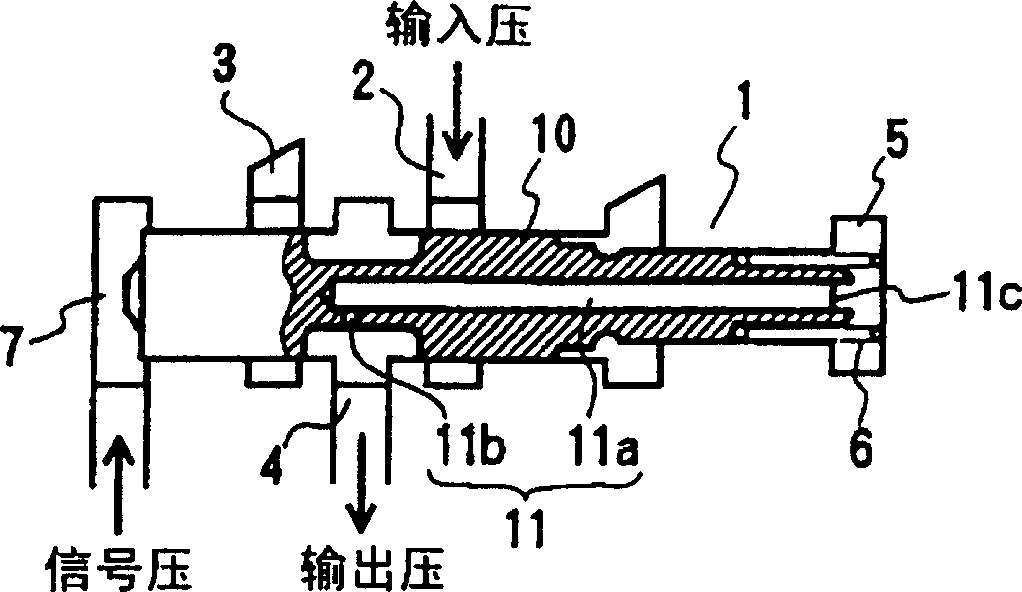
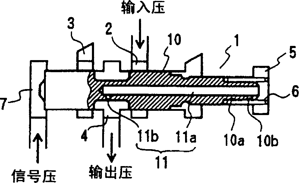
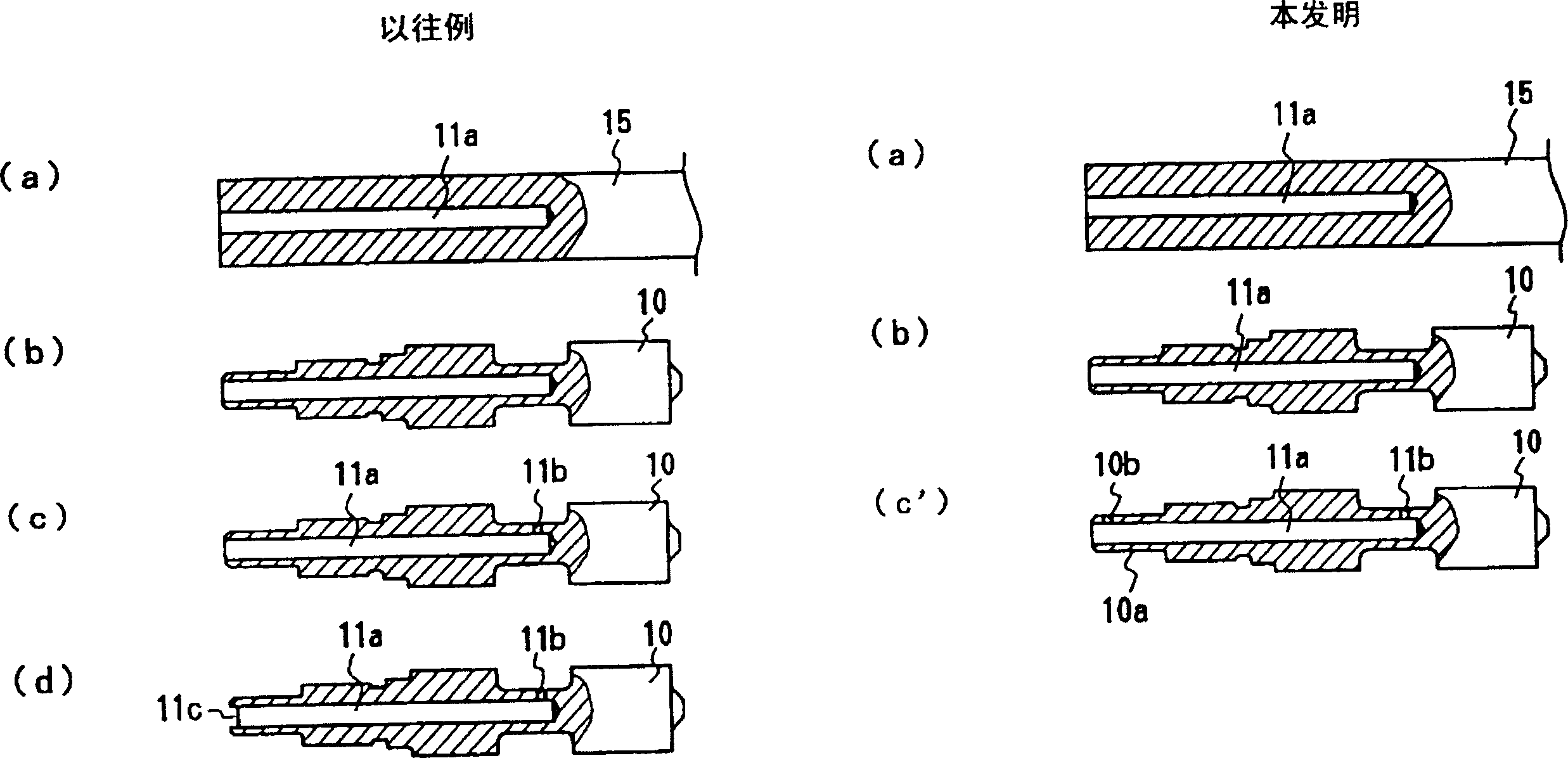
[0031] This pressure regulating valve has a valve body 20 and a spool valve 30 that can move freely in the valve body 20. In the valve body 20, there are input holes 21, discharge holes 22, output holes 23 and feedback holes 24, output holes 23 is provided between the input hole 21 and the discharge hole 22 , and the feedback hole 24 is provided at the end on the side of the input hole 21 and closed by a plug 25 . The spool valve 30 selectively communicates with the output hole 23 with the input hole 21 or the discharge hole 22 , and communicates with the output hole 23 and the feedback hole 24 through a communication hole 31 formed on the spool valve 30 . The communication hole 31 is composed of an axial center hole 31 a communicating with the feedback hole side of the spool valve 30 , and a passage hole 31 b processed radially from the position facing the output hole 23 to the axial center hole 31 a. When the feedback hole 24 feeds back the output pressure, since the communi...


PUM


Abstract

This pressure regulator comprises a valve body provided with an input port, a drain port, an output port and a feedback port, and the spool axially movably mounted in the valve body for selectively communicating the output port with the input port or the drain port, and the output port and the feedback port are communicated through a communication hole formed on the spool. The communication hole has a shaft center hole communicated with the feedback port formed on a shaft center of the spool and an orifice hole for supplying the oil pressure of the output port to the shaft center hole, a small diameter part is formed on an end part facing to the feedback port, of the spool, and a hole of a diameter same as the orifice hole is formed between an outer peripheral face of the small diameter part and the shaft center hole.

Description

technical field [0001] The invention relates to a pressure regulating valve used in the oil pressure control of various oil pressure devices. Background technique [0002] There are many matching elements in the automatic transmission for vehicles, and by selectively matching one or several of these elements, a multi-stage speed change is obtained. As a pressure regulating valve for controlling the oil pressure of the matching elements, it is known as figure 1 valve shown. [0003] This pressure regulating valve has a valve body 1 and a spool valve 10 provided in the valve body 1 to be freely movable in the axial direction. Valve body 1 is composed of input hole 2, discharge hole 3, output hole 4, feedback hole 5 and signal hole 7. The output hole 4 is set in the middle between the input hole 2 and the discharge hole 3, the feedback hole 5 is set at the end on the side of the input hole 2, and the signal hole 7 is set at the other end opposite to the feedback hole 5, that ...

Claims


Application Information

Patent Timeline
IPC IPC(8): F16K3/26F16K11/07F16K17/00G05D16/04G05D16/10
Inventor 妻藤靖
Owner DAIHATSU MOTOR CO LTD
Why Eureka
Try Eureka