Automotive lamp unit and making method thereof

A technology for car lights and headlights, applied to the field of car light units and their manufacturing, can solve problems such as inability to guarantee bonding strength, and achieve the effects of improving appearance quality, preventing slippage, and enhancing bonding strength

Inactive Publication Date: 2004-07-14
KOITO MFG CO LTD
View PDF1 Cites 5 Cited by
  • Summary
  • Abstract
  • Description
  • Claims
  • Application Information

AI Technical Summary

Problems solved by technology

Therefore, the end surface 2b of the bead 2a and the receiving surface 4a cannot be bonded with uniform pressure in t...

Method used


Image

  • Automotive lamp unit and making method thereof
  • Automotive lamp unit and making method thereof
  • Automotive lamp unit and making method thereof

Examples


Embodiment Construction

[0031] Some preferred embodiments of the present invention will be described below with reference to the accompanying drawings.

[0032] A first embodiment of the present invention will be described below.

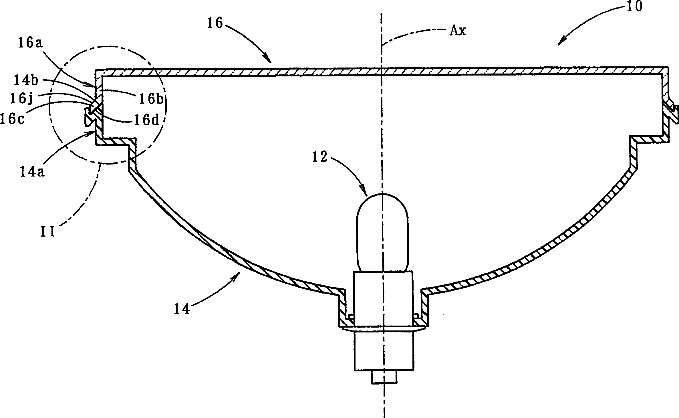
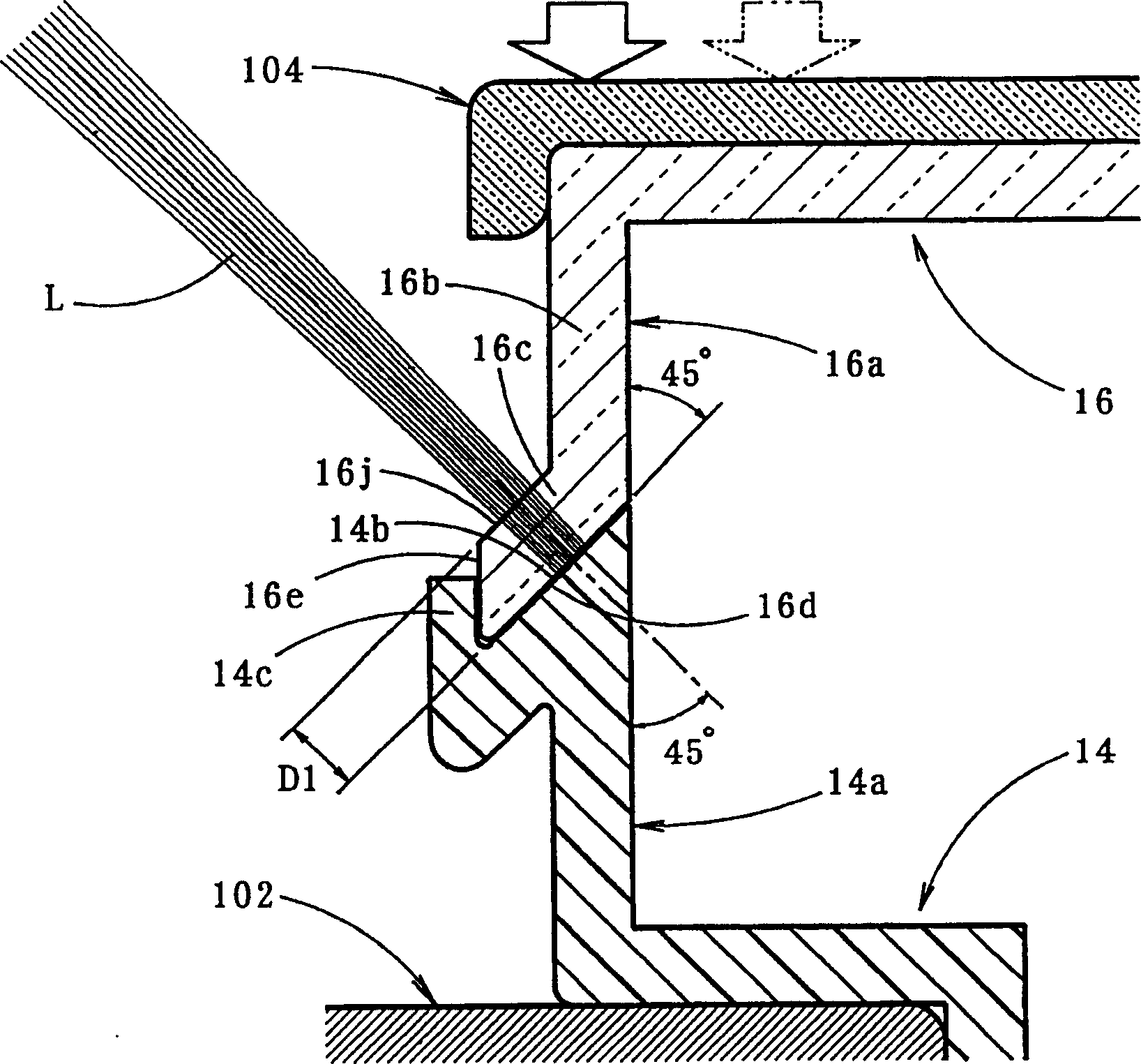
[0033] figure 1 is a side sectional view of the vehicle light unit according to the first embodiment of the present invention, the top of the vehicle light in the figure is facing upward. figure 2 is detailed display figure 1 View of Part II shown in .

[0034] As shown in these views, the vehicle light unit 10 is implemented as a signal light, such as a tail light. The car lamp unit 10 includes a lamp body 14, the light source bulb 12 is installed on the reference axis of the lamp, the extension direction of the bulb is vertical in the figure (it is in the longitudinal direction relative to the car lamp unit when installed on the vehicle), and the front The lamp glass 16 is bonded directly on the lamp body 14 .

[0035] The headlight glass 16 is made of a transpar...


PUM


Abstract

A vehicular lamp in which bonding failure between a front lens and a lamp body is prevented while enhancing the bonding strength and improving the quality of the outer appearance around the bonded surface therebetween. An end surface of a seal leg of a front lens and a receiving surface of a lamp body are bonded through laser beam welding so as to improve the outer appearance quality of the area around the bonded surfaces. The end surface is formed on an end portion of the seal leg that is bent and extended outward at a predetermined angle with respect to the bonding direction. The laser beam is irradiated onto the receiving surface through the end portion from a direction substantially orthogonal to the end surface. The resultant permeation distance of the laser beam is made short, resulting in a sufficient amount of irradiation energy. When pressure is applied to the base end portion of the seal leg by pressing on the front lens, the end surface and the receiving surface are brought into abutment in the width direction with uniform pressure.

Description

technical field [0001] The invention relates to a vehicle lamp unit and a manufacturing method thereof, wherein the headlight glass and the lamp body are directly bonded together. Background technique [0002] Conventionally, two types of methods for bonding the headlight glass and the lamp body of a vehicle lamp unit are known, that is, an indirect bonding method via a sealing device (for example, a heat-melt sealing method) and a bonding method by directly bonding the two devices. Direct bonding in close proximity (eg, hot plate welding, vibration welding, ultrasonic welding, etc.). [0003] As a direct bonding method, laser beam welding is known in other fields. Such a method is also suitable for bonding headlight glass and lamp body. One such process would refer to Figure 8 described (see also co-pending US patent application Ser. No. 09 / 548361 with common assignee). [0004] refer to Figure 8 , forming a sealing edge 2a extending in the outward direction along the ...

Claims


Application Information

Patent Timeline
IPC IPC(8): F21S8/10B29C65/00B29C65/16F21V5/00F21V17/00F21V17/10F21W101/10F21W101/12F21W101/14
CPCB29K2055/02B29C65/1616B29C65/1635F21S48/2212B29C66/50B29C66/12449B29C65/169B29C65/16B29C66/1312B29C66/301F21V17/101B29C66/534B29K2101/12B29C66/114B29C66/54B29C65/1654B29K2069/00B29C66/81267B29C65/1687B29L2031/747B29C65/1677B29C66/12464F21S48/255B29C66/1142B29K2033/12B29C66/542B29K2995/0072B29C66/112B29C66/12469B29C66/545B29C66/652B29C66/71B29C66/712B29C66/73343B29C66/73361B29C66/73365B29C66/73921B29C66/81423B29C66/8322B29C66/836B29C66/863B29K2995/0027B29L2031/30F21S43/26F21S43/51B29K2025/08
Inventor 秋山一夫杉山富士彦
Owner KOITO MFG CO LTD
Why Eureka
Try Eureka