
Use of catalyst in standby valve-regulated lead acid cell

A catalyst and battery technology, applied in the direction of lead-acid batteries, secondary batteries, battery components, etc.

Inactive Publication Date: 2004-08-25
PHILADELPHIA SCI
View PDF4 Cites 0 Cited by
  • Summary
  • Abstract
  • Description
  • Claims
  • Application Information

AI Technical Summary

Problems solved by technology

The specific gas recovery unit disclosed does not have a pressure relief valve
Also, the Marui et al. reference does not have a breathable hydrophobic coating surrounding the container, which states that water can pass through the catalyst container and provide it with a non-hydrophobic specific container portion (see column 5, lines 15-18)
This reference does not address valve regulated batteries

Method used


Image

  • Use of catalyst in standby valve-regulated lead acid cell
  • Use of catalyst in standby valve-regulated lead acid cell
  • Use of catalyst in standby valve-regulated lead acid cell

Examples


Embodiment Construction

[0042] A. Use of Catalyst

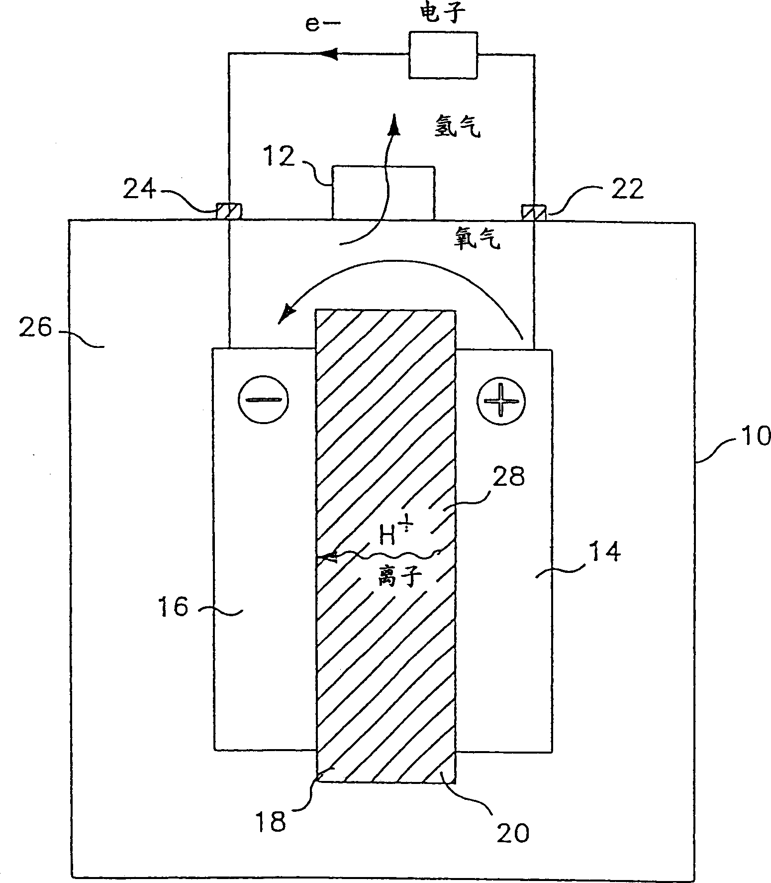
[0043] see figure 1 , the VRLA battery of the present invention has a sealed casing 10 provided with a pressure relief (one-way) valve 12 . A positive electrode 14 having an active material is located within the housing 10 . A negative electrode 16 having an active material is also located within housing 10 and is spaced apart from the positive electrode. These electrodes are generally plate-shaped. An electrolyte-containing separator assembly 18 is sandwiched between the positive and negative electrodes and an electrolyte 20 is contained within the separator assembly. Virtually all of the electrolyte is contained within the separator assembly, there is no "free" electrolyte in the battery.

[0044] The most widely used VRLA batteries are considered to include the following: a positive electrode comprising a conductive material such as a lead alloy, preferably a lead-calcium alloy, and an active material consisting of PbO; a negative electrode c...


PUM

PropertyMeasurementUnit
Thicknessaaaaaaaaaa
Outer diameteraaaaaaaaaa

Abstract

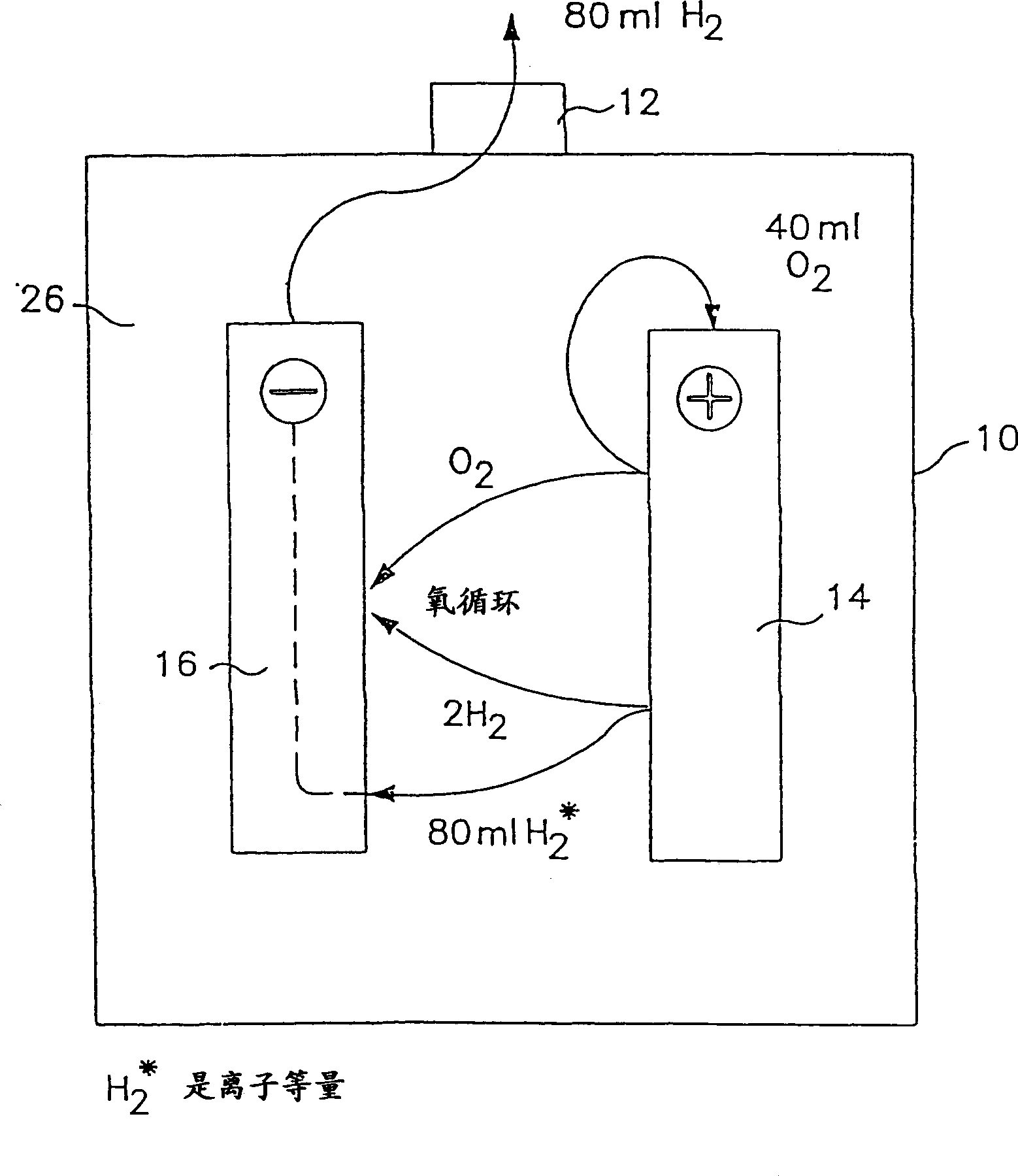
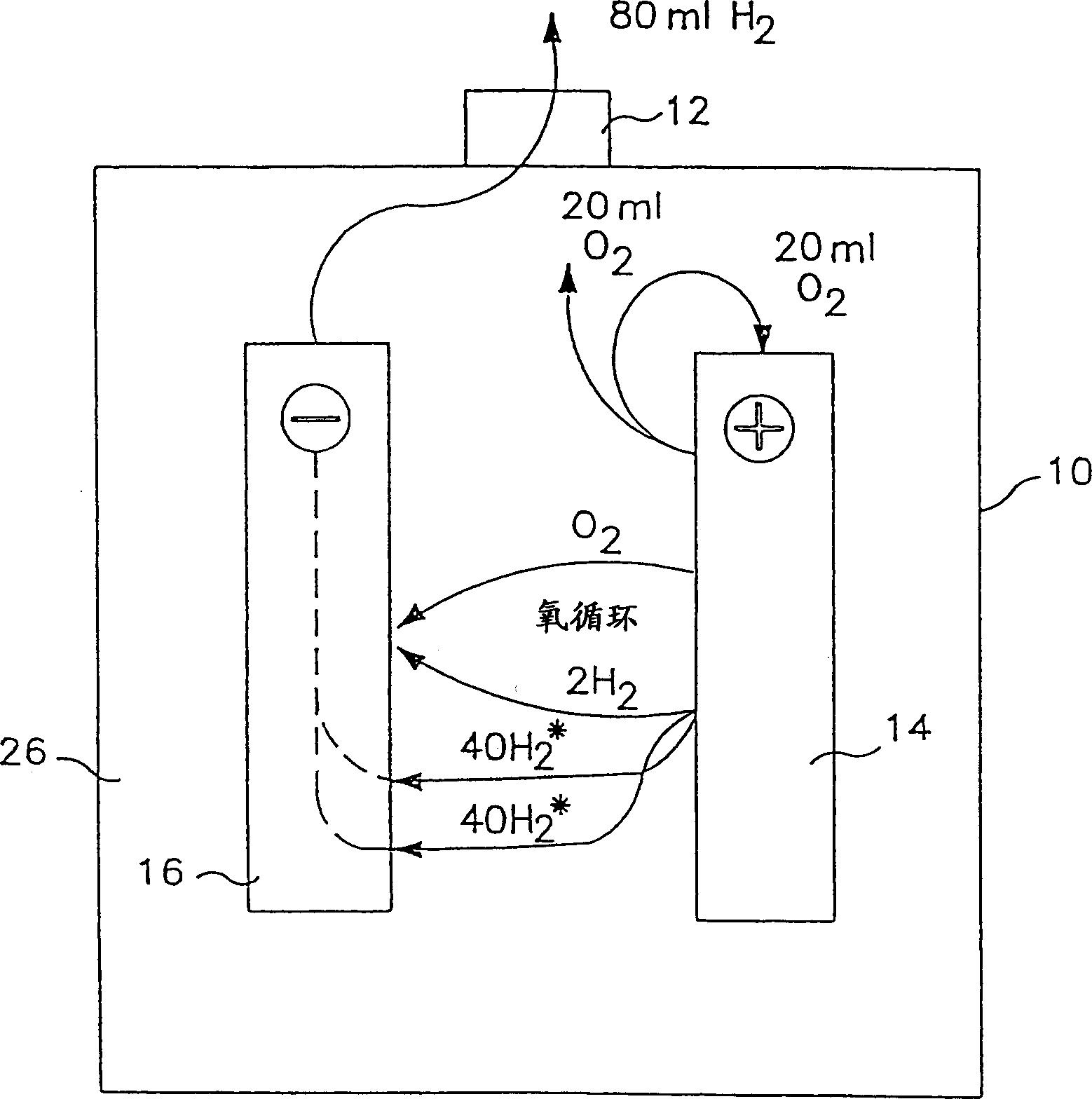
In the charging of a valve-regulated, lead-acid (VRLA) cell at a charge voltage which has a value that is slightly in excess of the value of the open-circuit voltage of the cell, wherein, during charging of the cell, there is produced at the positive and negative electrodes respectively oxygen gas and hydrogen gas in a predetermined amount, and wherein the negative electrode tends to discharge over a prolonged period of time during charging, the improvement comprising inhibiting the tendency of the negative electrode to discharge during charging by controlling the amount of oxygen gas in the cell by catalytically converting a portion of the oxygen gas and a portion of the predetermined amount of hydrogen gas to water, for example, by use of a catalyst positioned in the cell.

Description

[0001] related application [0002] This application is a continuation-in-part of International Application No. PCT / US97 / 20445, filed November 12, 1997, which claims the benefit of US Provisional Application No. 60 / 030854, filed November 12, 1996. technical field [0003] This invention relates to the use of catalysts to increase the useful life of backup valve-regulated lead-acid (VRLA) batteries, and to a catalyst device applicable to other batteries which preferably recombine excess oxygen with hydrogen produced in the battery. Background technique [0004] The structure of the VRLA battery is in figure 1 indicated in the middle. Like a typical flooded cell, there are at least two electrodes or plates: a positive plate and a negative plate. Each plate consists of a grid to collect current and an active material to store energy. However, VRLA batteries differ from flow batteries in two ways. [0005] First, instead of submerging the plates in a liquid bath of electroly...

Claims


Application Information

Patent Timeline
IPC IPC(8): H01M2/12H01M10/06H01M10/44H01M10/52
CPCH01M2/127H01M2/1264H01M2/1205H01M2/12H01M10/523H01M10/44H01M2/1229H01M10/121Y02E60/126H01M10/52Y02E60/10H01M50/30H01M50/308H01M50/325H01M50/383H01M50/394
Inventor 威廉E·M·琼斯H·A·瓦纳斯J·克拉珀C·E·萨波塔E·F·普里斯
Owner PHILADELPHIA SCI
Learn More