Pipe coupling

A technology of pipe joints and joints, applied in the field of pipe joints, can solve the problems of air leakage and incomplete sealing, and achieve the effects of improving performance, improving air tightness and improving rigidity

Inactive Publication Date: 2004-09-15
SMC CORP
View PDF0 Cites 0 Cited by
  • Summary
  • Abstract
  • Description
  • Claims
  • Application Information

AI Technical Summary

Problems solved by technology

[0003] However, in the cut product of the above-mentioned metal material, the surface roughness of the inner surface of the housing portion of the sealing member of the joint body does not necessarily reach a value suitable for sealing, and depending on the occasion, there may be a gap between the sealing member and the housing portion of the joint body. Leakage of air (even if it is small) In addition, in the cut product, the chips generated during processing are attached to the inner surface of the sealing member housing. After assembly, even if the processing is performed properly, it may become a defective product with incomplete sealing.
[0004] In addition, in the above-mentioned conventional pipe joints, a synthetic resin guide member is usually quickly joined in a joint body made of a metal material. In this case, the strength of the pipe joint is often dominated by the temperature of the synthetic resin guide member. In various application fields, there is a strong demand for improvement in strength, thermal characteristics, and durability

Method used


Image

  • Pipe coupling
  • Pipe coupling
  • Pipe coupling

Examples


Embodiment Construction

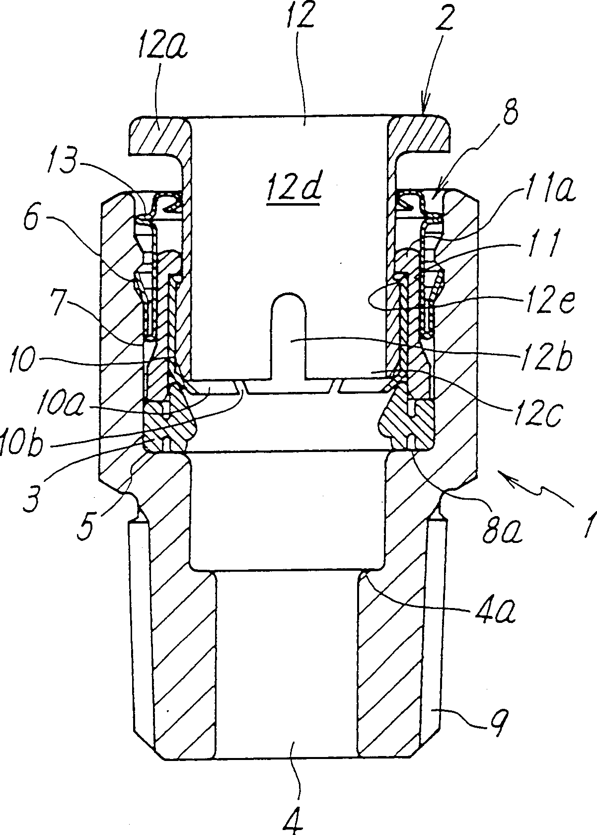
[0018] figure 1 An example of the pipe joint of the present invention is shown. The pipe joint of this embodiment has a joint main body 1 forming the outer peripheral portion of the pipe joint, a pipe holding mechanism 2 for holding the pipe end assembled in the joint main body 1, and a pipe holding mechanism 2 accommodated in the joint. The elastic sealing member 3 inside the body 1 .

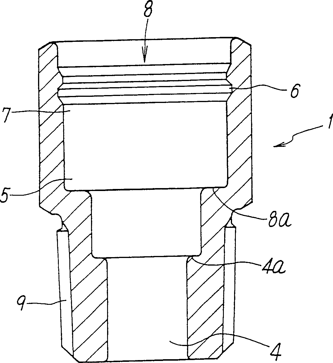
[0019] The above-mentioned joint body 1 is formed by cold forging of iron-based metal materials. figure 2 It can be seen that a fluid flow path 4 is provided through the joint body 1 in the axial direction, and the fluid flow path 4 allows fluid to flow between the pipe and the hydraulic pressure machine. On one end side of the fluid flow path 4 of the joint body 1, an enlarged diameter The recessed portion 8 has the receiving portion 5 for the seal member on the inner side and the receiving portion 7 for the tube holding mechanism on the mouth side, and has the engagement groove 6 for the t...


PUM


Abstract

A pipe joint is provided having, at one end of a fluid passage 4 passing through the inside of a joint body 1, a diametrally expanded recess 8 that defines a seal member storage portion 5 on the inner side and a tube holding mechanism storage portion 7 on the mouth side where a locking groove 6 of a tube holding mechanism 2 runs and the joint body 1 is constructed as a cold-forged component of a metal material. An elastic seal member 3 is seated in the seal member storage portion 5. In the locking groove 6 of the tube holding mechanism storage portion 7 elastically locks in anti-separation fashion a sharp-edged locking portion 13b formed by an outward fold extending from a back-side projection of a guide member 13 of springy metal material disposed outside the tube holding mechanism.

Description

technical field [0001] The invention mainly relates to pipe couplings (quick couplings) for the connection of various machines to pipes in air circuits. Background technique [0002] In the prior art, as a pipe joint (quick joint) used in an air pressure circuit, there is known a pipe joint in which a joint body forming its outer peripheral portion is formed of a metal material. The joint body is usually provided with a fluid flow path through the inside, and an enlarged diameter recess is provided on one end side of the fluid flow path, and is formed by cutting of a metal material such as brass. part, with the mouth side as the tube holding mechanism. [0003] However, in the cut product of the above-mentioned metal material, the surface roughness of the inner surface of the housing portion of the sealing member of the joint body does not necessarily reach a value suitable for sealing, and depending on the occasion, there may be a gap between the sealing member and the hou...

Claims


Application Information

Patent Timeline
Patent Type & Authority Patents(China)
IPC IPC(8): F16L37/12F16L37/08F16L37/091
CPCF16L37/091F16L37/0915F16L37/08
Inventor 中角正洋森玄夫
Owner SMC CORP
Why Eureka
Try Eureka