
Connector assembly with shielded modules and method of making same

A technology of electrical connectors and modules, applied in the direction of two-part connection devices, parts of connection devices, connections, etc.

Inactive Publication Date: 2004-12-08
THE WHITAKER CORP
View PDF4 Cites 33 Cited by
  • Summary
  • Abstract
  • Description
  • Claims
  • Application Information

AI Technical Summary

Problems solved by technology

[0003] The problem of impedance matching of terminal contacts has been discussed in U.S. Patent No.5066 236 and No. 5496183, which also discusses low-cost and simple-designed right-angle connectors. Although the modular design in this regard is convenient for producing shorter or longer It is not necessary to redesign and process a new connector, but it can only produce a new housing part to assemble many consistent terminal modules in it.

Method used


Image

  • Connector assembly with shielded modules and method of making same
  • Connector assembly with shielded modules and method of making same
  • Connector assembly with shielded modules and method of making same

Examples


Embodiment Construction

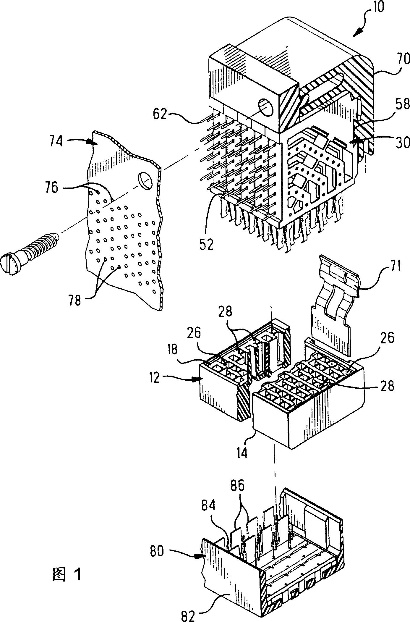
[0030] Figure 1 shows a connector 10 having a housing 12 and a plurality of shielded terminal modules 30 prepared in accordance with the present invention. The connector 10 is shown exploded from a circuit board or backplane 74 . The chassis 12 includes a mating surface 14 , a mounting surface 16 , a mounting surface 18 , a plurality of signal contact receiving channels 26 , and a plurality of ground contact receiving channels 28 extending from the mounting surface 18 to the mating surface 14 . The signal contact channel 26 includes an aperture 27 in the mating face 14 for receiving a complementary signal contact 84 of a mating connector 80 . The ground contact channel 28 includes a slot 29 in the mating face 14 for receiving a complementary ground contact 86 of the mating connector 80, such as Figure 6 and 7.

[0031] Mating connector 80 includes a housing 82 having a plurality of signal contacts 84 arranged in a staggered array complementary to the array of signal contacts...


PUM


Abstract

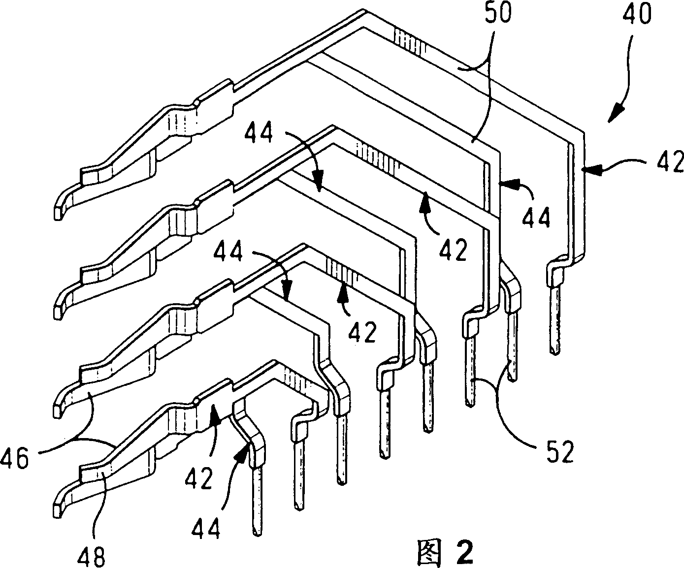
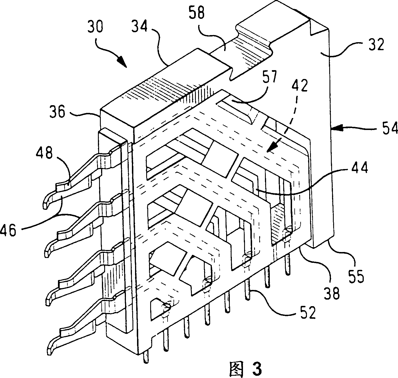
An electrical connector assembly (10) includes an insulating housing (12) and assembled thereto a plurality of terminal modules (30) and electrically conductive shields (60) therebetween. Each terminal module (30) includes an alternating pattern of first and second contacts (42, 44), the intermediate portions (50) thereof being formed at selected locations therealong such that the intermediate portions of the first contacts (42) are encapsulated in the insulating web (54) proximate a first side surface (32) and the intermediate portions of the second contacts (44) are encapsulated in the web (54) proximate the second major surface (34) of the module. In the assembled connector (10), the first contacts (42) are spaced more closely to shield (60) along surface (32) and the second contacts (44) are spaced more closely to shield (60) along surface (34) thereby assuring primary coupling between each signal contact (40) and a respective ground shield (60) rather than to an adjacent signal contact (40).

Description

technical field [0001] The present invention relates to an electrical connector assembly having a shield module for shielding rows of adjacent terminals from crosstalk. Background technique [0002] In the electronics industry, a right-angle connector is generally used as an electrical connection between two printed circuit boards or between a printed circuit board and a wire. Such right-angle connectors typically have a large number of pin-receiving terminals and pins (eg, flex pins) at right angles thereto that make electrical contact with the printed circuit board. A post or post connector on another printed circuit board may then be inserted into the pin-receiving terminal to form an electrical connection therebetween. The frequency of electrical signal transmission through these connectors is very high, which not only requires matching impedance with the circuit board and balanced capacitance at each contact in these terminal modules to reduce signal lag and reflection...

Claims


Application Information

Patent Timeline
IPC IPC(8): H01R12/50
CPCH01R23/688H01R13/6587
Inventor S·K·米基韦茨R·N·惠内
Owner THE WHITAKER CORP
Learn More