Piezoelectric ceramic composition

A technology of piezoelectric ceramics and compositions, applied in ceramics, circuits, piezoelectric/electrostrictive/magnetostrictive devices, etc., can solve problems such as inability to apply, inability to use sensors in products, and increase in mechanical quality factor Qm

Inactive Publication Date: 2005-01-05
TDK CORPARATION
View PDF3 Cites 0 Cited by
  • Summary
  • Abstract
  • Description
  • Claims
  • Application Information

AI Technical Summary

Problems solved by technology

[0010] JP-B-54-267116 and JP-B-54-26717 propose a method that adds MnO 2 In order to improve the mechanical strength, but the problem is that this method increases the mechanical quality factor Qm, so that the product cannot be used on this type of sensor
[0011] Also,

Method used


Image

  • Piezoelectric ceramic composition
  • Piezoelectric ceramic composition
  • Piezoelectric ceramic composition

Examples


Embodiment Construction

[0026] Examples of the present invention are described below.

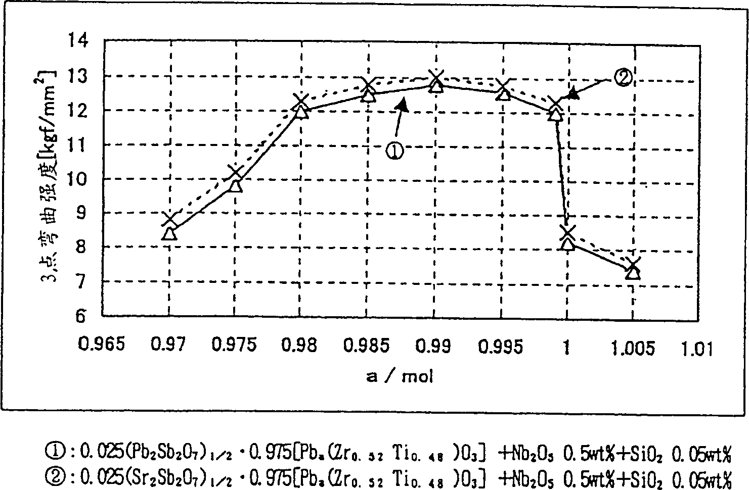
[0027] Using chemically pure PbO, TiO 2 , ZrO 2 , Sb 2 o 5 , Nb 2 o 5 , Ta 2 o 5 , WO 3 , BaCO 3 , and SrCO 3 As starting materials, the components listed in Tables 1 and 2 were weighed and wet milled with a ball mill. Then, the mixed particles are calcined briefly at 850° C.-950° C. in air, and then wet-milled into powder using a ball mill.

[0028] Thereafter, the powder thus obtained was added with an organic binder and granulated at 2000 kg / cm 2 A disk-like structure with a diameter of 15 mm and a thickness of 1.5 mm was formed under pressure. The formed product is calcined at 1100°C-1240°C under atmospheric pressure.

[0029] The surface of the sintered product obtained above was ground to a thickness of 1.0 mm and processed to a diameter of 10 mm. Then, after forming the silver-fired electrodes, the sintered product was subjected to polarization treatment in the thickness direction for 30 minut...


PUM


Abstract

There is provided a composition of piezoelectric porcelain which is composed as x (Me2Sb2O7)1/2.(1-x) ÄPba(ZryTiz)O3Ü (provided that 0.98</=a</=0.999, 0.005</=x</=0.05, 0.50</=y</=0.54, 0.46</=z</=0.50, y+z=1) being the main component where Me is Pb or at least one of Ba and Sr, and to the weight of 1 mol of the main component, 0.1 to 1.0 wt% of at least one kind of W, Sb, Nb, and Ta in terms of WO3, Sb2O3, Nb2O5, and Ta2O5 is added as a sub component, and 0.01 to 0.1 wt% of Si in terms of SiO2 is added as a further sub component.

Description

(1) Technical field [0001] The present invention relates to a piezoelectric ceramic composition for use in a ceramic piezoelectric sensor for detecting vibration, and in particular, a piezoelectric ceramic composition suitable for detecting vibration of an automobile engine. (2) Background technology [0002] When a piezoelectric ceramic sensor for detecting vibration uses a piezoelectric ceramic composition, the composition is required to have a high electromechanical coupling factor kt (for example, 50% or more) and a large specific permittivity (for example, , 1000 or more) characteristics. [0003] Since the sensitivity of the sensor to ambient temperature changes is to be stabilized, it is desirable that the change in piezoelectric properties such as electromechanical coupling factor, capacitance, etc. is a small change independent of temperature change (for example, in terms of electromechanical coupling factor, when the temperature is The electrical coupling factor i...

Claims


Application Information

Patent Timeline
IPC IPC(8): C04B35/49C04B35/493H01L41/187
CPCC04B35/493H01L41/1876H10N30/8554
Inventor 佐佐木诚志
Owner TDK CORPARATION
Why Eureka
Try Eureka