Supercharge Your Innovation With Domain-Expert AI Agents!

Method for guiding are by laser, and are guiding welding and device by the method

A welding method and welding equipment technology, applied in laser welding equipment, arc welding equipment, welding equipment, etc., can solve problems such as hard-to-inductive arcs

Inactive Publication Date: 2005-03-23
NIHON KENKI CO LTD
View PDF1 Cites 0 Cited by
  • Summary
  • Abstract
  • Description
  • Claims
  • Application Information

AI Technical Summary

Problems solved by technology

Therefore it is difficult to correctly induce the arc in TIG welding

Method used


Image

  • Method for guiding are by laser, and are guiding welding and device by the method
  • Method for guiding are by laser, and are guiding welding and device by the method
  • Method for guiding are by laser, and are guiding welding and device by the method

Examples


Embodiment Construction

[0065] Embodiments of the present invention will be described below with reference to the drawings.

[0066] First, the principle of the present invention will be explained.

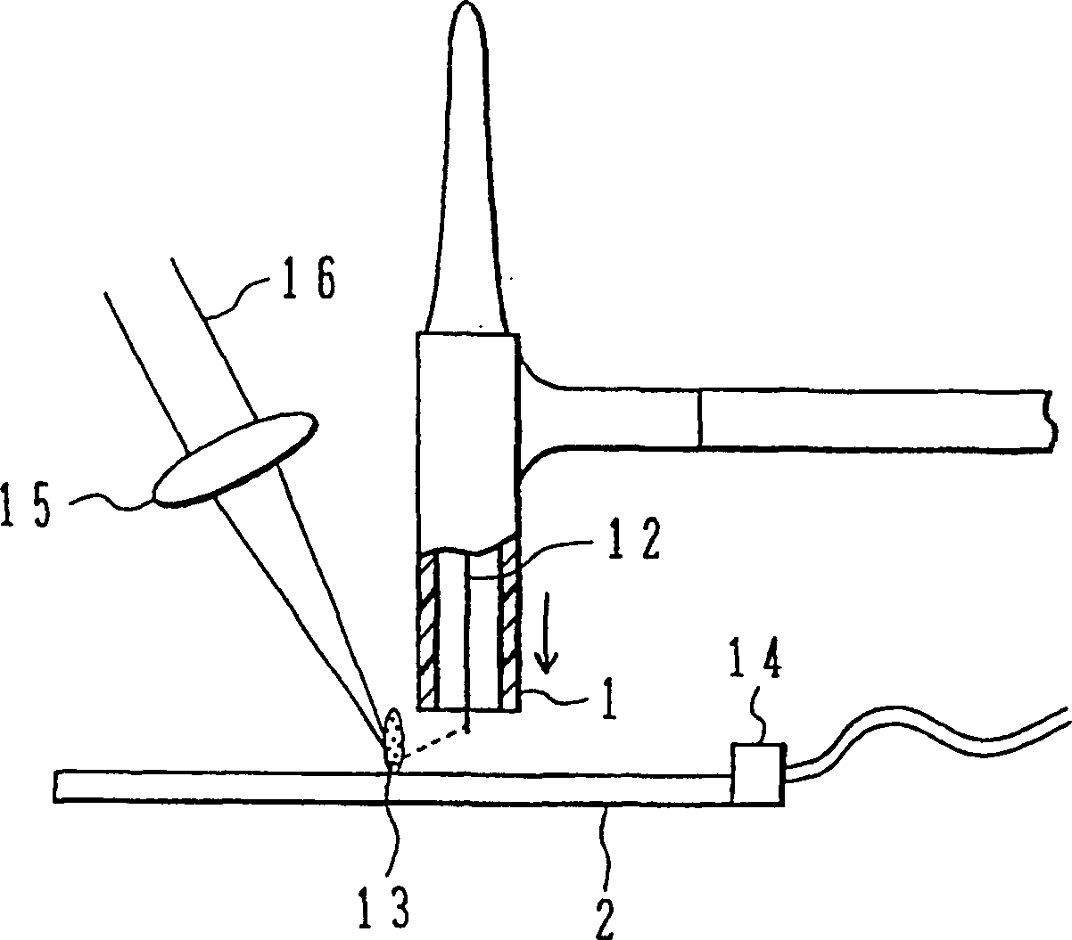
[0067] The arc induction phenomenon by laser is the phenomenon of floating (pul-mu) composed of ionized metal vapor and thermal electrons in the laser irradiation part by laser irradiation. Compared with the air in the basic insulating state, due to the occurrence of this floating , the impedance between the torch electrode and the laser irradiated part of the base metal will decrease, and at the same time, the part of the base metal irradiated by the laser will be heated to release thermal electrons, so an arc discharge will be induced in the laser irradiated part.

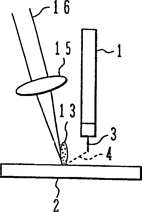
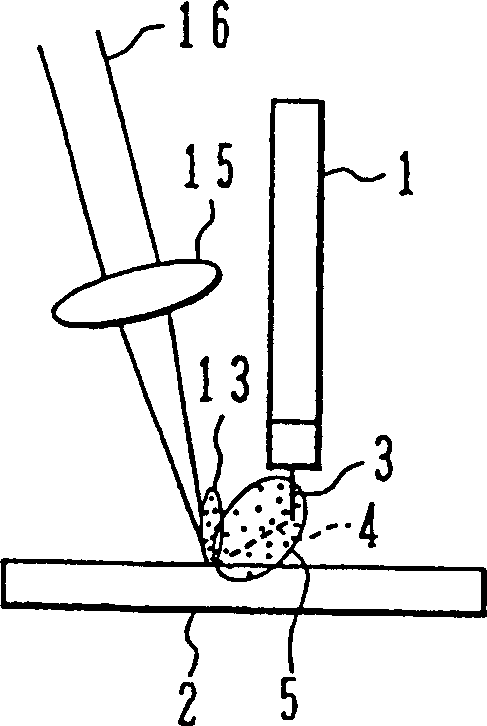
[0068] Fig. 1 illustrates the principle of the present invention by taking the induction of arc discharge in TIG welding as an example.

[0069] In FIG. 1 , a welding torch 1 is a torch for TIG welding, and an alternating voltage or a puls...


PUM


Abstract

A plasma (13) is produced in a position where the parent metal (2) is to be welded by a laser beam (16) applied to the parent metal. An arc discharge (4) occurs in the direction toward the plasma (13) when the discharge electrode (12) is negative and is guided to the position where the laser beam (16) is applied. Arc electrons are produced at the point where the laser beam (16) is applied when the electrode (12) is positive, and electric discharge is caused toward the electrode (12). If the voltage applied to the electrode (12) and the parent metal (2) is an AC voltage, the polarities of the electrode (12) and the parent metal (2) alernate, causing the phenomena to alternate. If the parent metal (2) is negative, an arc discharge (4) occurs from the laser beam spot. Since the arc discharge (4) is caused from the plasma (13) produced by the laser beam (16), the arc discharge (4) is stable irrespective of the states of the parent metal (2) and electrode (12).

Description

technical field [0001] The present invention relates to arc discharge induction using laser and welding method and apparatus for arc induction of laser in narrow grooves by arc welding. Background technique [0002] In arc welding, there are TIG (tungsten inert gas) welding, MIG (metal inert gas) welding, CO 2 , MAG (metal active gas) welding, etc. In addition to TIG welding, in MIG welding and the like, when moving the arc generation position, generally, as shown in FIG. In addition, in TIG welding, the electrode is different from the filler, and the arc is moved by moving the tungsten electrode relative to the base material to be processed. TIG welding uses non-consumable electrodes while MIG welding uses consumable electrodes. [0003] For example, in the method described in JP-A-5-146877, as shown in FIG. 16, the feed wire is bent by the filler bending gear 6, moved to the position of the arc discharge 4, and welded. [0004] Another example Figure 17 The welding me...

Claims


Application Information

Patent Timeline
IPC IPC(8): B23K9/067B23K9/073B23K26/14B23K28/02
CPCB23K9/0675B23K26/1423B23K28/02B23K9/073B23K26/348B23K9/067
Inventor 樱井茂行高野悠敬三柳直毅下村义昭山本光高谷透
Owner NIHON KENKI CO LTD
Features
  • R&D
  • Intellectual Property
  • Life Sciences
  • Materials
  • Tech Scout
  • Unparalleled Data Quality
  • Higher Quality Content
  • 60% Fewer Hallucinations
Learn More