
Planar second-order magnetic field gradient meter in new structure

A new type of structure, plane two technology, applied in the field of superconducting quantum interference devices, can solve the problem of low yield and high

Inactive Publication Date: 2005-06-29
INST OF PHYSICS - CHINESE ACAD OF SCI
View PDF0 Cites 1 Cited by
  • Summary
  • Abstract
  • Description
  • Claims
  • Application Information

AI Technical Summary

Problems solved by technology

For high-temperature superconducting thin films, the quality of the edge of the film is generally not as good as that in the middle, so the yield of SQUID at the edge is not high

Method used


Image

  • Planar second-order magnetic field gradient meter in new structure
  • Planar second-order magnetic field gradient meter in new structure
  • Planar second-order magnetic field gradient meter in new structure

Examples


Embodiment 1

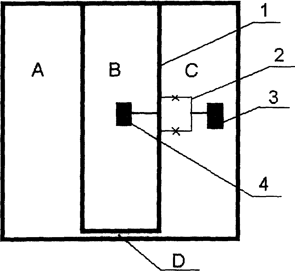
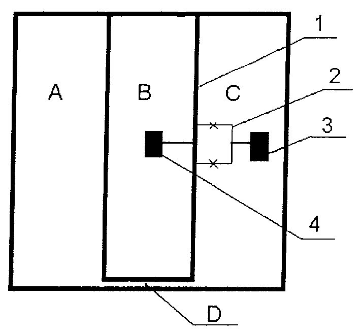
[0016] Embodiment 1: Make a planar second-order magnetic field gradiometer according to Fig. 2 .

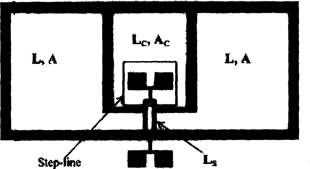
[0017] The high temperature superconducting film is photoetched into two closed loops. One of the closed loops is composed of open loop A, open loop C and connecting channel D, and the other closed loop is B. Line 1 is the common part of closed loop B and closed loop ACD. The area and shape of the open loop A, the open loop C and the closed loop B are all the same, and the area of ​​the connecting channel D is as small as possible.

[0018] At the same time, a SQUID2 is photo-etched on the side of the line 1 to couple with the line 1. SQUID2 is supplied with bias current by electrodes 3,4. Thus a planar second-order magnetic field gradiometer is formed.


PUM


Abstract

The invention relates to the technical field of superconducting quantum interference devices (SQUID). The invention adopts double closed-loop detection coils, makes the current of the common part of the two closed loops proportional to ΦA-2ΦB+ΦC, couples with SQUID, and obtains a second-order magnetic field gradiometer. The present invention has a simple structure; as long as the SQUID can be coupled with the line 1, the present invention has no strict requirements on the position of the SQUID; multiple SQUIDs can be coupled with the line to improve the yield.

Description

technical field [0001] The invention relates to the technical field of superconducting quantum interference devices (SQUID). Background technique [0002] Superconducting quantum interference devices (SQUIDs) are very sensitive magnetic field detection devices. In many applications, in order to reduce the impact of environmental stray magnetic fields (such as the earth's magnetic field and space electromagnetic waves), gradiometers are usually used. For high-temperature superconductors, since there is no superconducting wire, the traditional gradient coil method cannot be used to form a gradiometer. At present, for high-temperature superconductors, SQUID gradiometers are realized in two forms: the first is called electronic gradiometer; the second is called planar gradiometer. The electronic gradiometer is composed of two or more SQUID magnetometers, and the gradiometer is obtained by subtracting the output signals of the SQUID magnetometers by electronic methods. It has ...

Claims


Application Information

Patent Timeline
Patent Type & Authority Patents(China)
IPC IPC(8): G01R33/022G01R33/035
Inventor 郎佩琳郑东宁陈珂漆汉宏赵忠贤
Owner INST OF PHYSICS - CHINESE ACAD OF SCI
Learn More