
Brake controller of elevator

A technology of elevator brakes and control devices, which is applied in the direction of brake actuators, circuits, electromagnets, etc., can solve problems such as increased noise, difficult detection of movable brake shoes, and uncomfortable elevator rides, so as to improve work efficiency. efficiency effect

Inactive Publication Date: 2005-11-30
MITSUBISHI ELECTRIC CORP
View PDF6 Cites 0 Cited by
  • Summary
  • Abstract
  • Description
  • Claims
  • Application Information

AI Technical Summary

Problems solved by technology

In this way, there is a problem that the noise generated by the above-mentioned impact will be increased.
[0014] Especially for elevators where the traction machine body is installed in the hoistway, there is a problem that the noise of the brake action is transmitted to the car 1, and there is a very uncomfortable feeling when taking the elevator.
Although this brake device involves reducing the noise of the brake operation, there is a problem that it is difficult to detect the position of the movable plate and the position of the brake shoe. Easy to change the consumption and brake adjustment
However, there is a problem that if the brake coil current is reduced, the brake will malfunction due to voltage fluctuations.

Method used


Image

  • Brake controller of elevator
  • Brake controller of elevator
  • Brake controller of elevator

Examples


Embodiment Construction

[0043] In order to explain the present invention in more detail, the present invention will be described below with reference to the accompanying drawings.

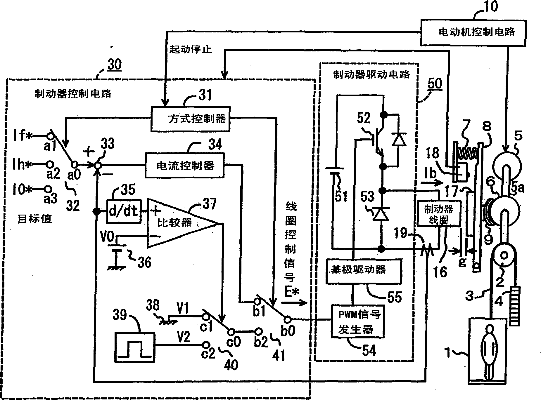
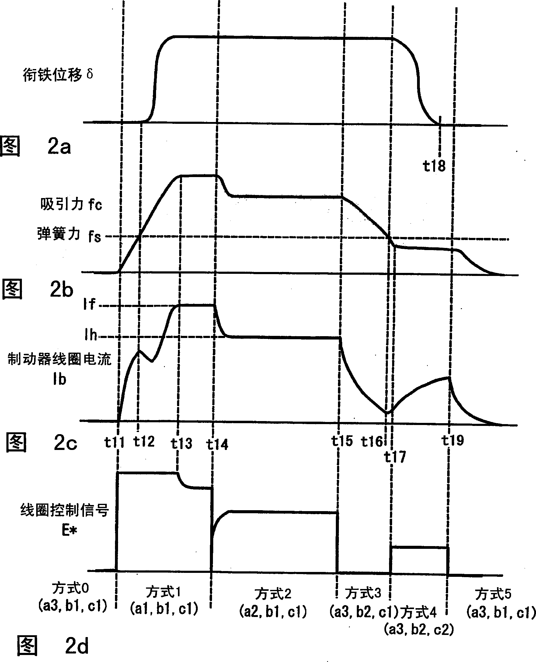
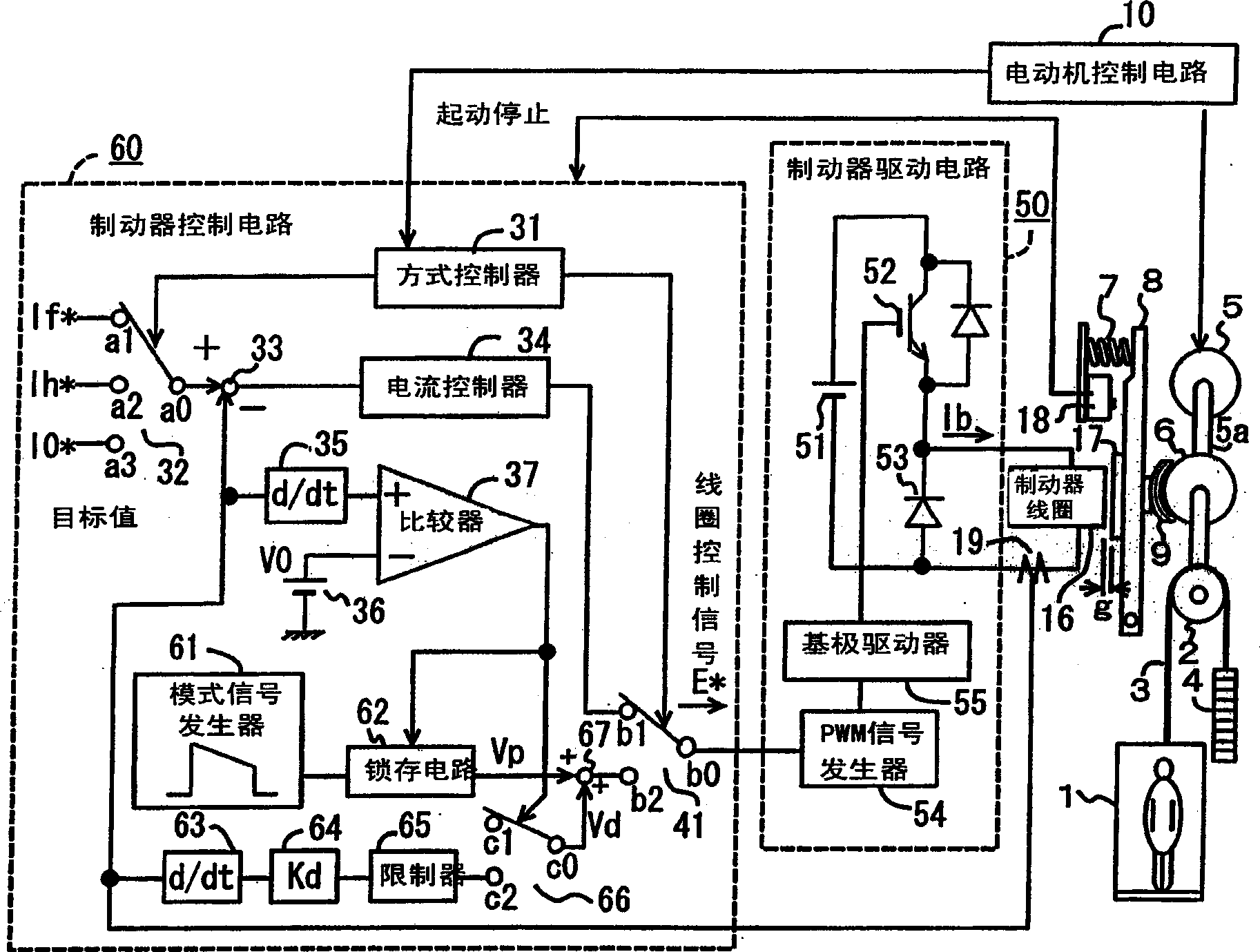
[0044] figure 1 and FIG. 2 shows a first embodiment of the elevator brake control device according to the invention. figure 1 is a block diagram showing the brake control circuit. In the figure, 1 is the car, 2 is the traction sheave of the traction machine, 3 is the main wire rope wound on the traction sheave 2, and 4 is suspended together with the car 1 by means of the main wire rope 3 The counterweight of hanging, 5 is the traction motor that rotates and drives the traction wheel 2 through the shaft 5a, and 6 is the brake wheel that is directly connected with the shaft 5a.

[0045] 7 is a spring, which usually presses the brake shoe 9 on the outer peripheral surface of the brake wheel 6 through the brake arm 8, and uses friction to generate braking force. 10 is the motor control circuit for controlling the traction...


PUM


Abstract

When an armature is attracted while resisting against a spring; by energizing a brake coil and a brake shoe; pressing a brake wheel is released to generate brake force in the released brake of an elevator, energization of the brake coil; is reduce, at first, by a first brake coil control means to release attraction of the armature. When the reduction rate of a brake coil current; slows down to a specified level or below or the brake coil current, begins to increase during the attraction releasing process of the armature; by the first brake coil control means a switching is made to a second brake coil control means and the brake coil, is energized within such a range as the armature is not reattracted thus suppressing impact sound of the brake shoe; against the brake wheel, generated by the force of the spring.

Description

technical field [0001] The invention relates to the brake control of an elevator. When there is an elevator start signal, the energized circuit is connected, and the brake coil is energized, so that the armature is attracted against the spring force, and the result of this attraction is used to release the brake shoe against the brake wheel. Press to release the braking force, and the elevator can start; when there is a stop signal, the energized circuit is disconnected, the armature is released, and the spring is used to press the brake shoe to generate braking force. Background technique [0002] Fig. 10 shows a simplified structure of a general brake used in a rope elevator. The car 1 of the elevator is suspended together with the counterweight 4 by the main wire rope 3 wound on the traction sheave 2 of the traction machine, and is driven by the traction motor 5 . A brake pulley 6 is mounted on a shaft 5 a connecting the traction motor 5 and the traction sheave 2 . When...

Claims


Application Information

Patent Timeline
Patent Type & Authority Patents(China)
IPC IPC(8): B66B1/32F16D65/14F16D65/22F16D121/16F16D121/22F16D127/02F16D129/06H01F7/06H01F7/18
CPCH01F7/1805B66B1/32
Inventor 假屋佳孝安江正德渡边诚治
Owner MITSUBISHI ELECTRIC CORP
Learn More