Stepped engine frame

An engine, step-shaped technology, applied in the direction of engine components, machine/engine, engine lubrication, etc., can solve the problem of increasing the number of parts and processes

Inactive Publication Date: 2006-01-04
HYUNDAI MOTOR CO LTD
View PDF0 Cites 0 Cited by
  • Summary
  • Abstract
  • Description
  • Claims
  • Application Information

AI Technical Summary

Problems solved by technology

In order to install the oil filter, a separate mounting element (such as a bracket for providing a support for the oil filter) is usually used, resulting in an increase in the number of parts and the number of processes

Method used


Image

  • Stepped engine frame
  • Stepped engine frame
  • Stepped engine frame

Examples


Embodiment Construction

[0018] The present invention will now be described in detail with reference to the accompanying drawings.

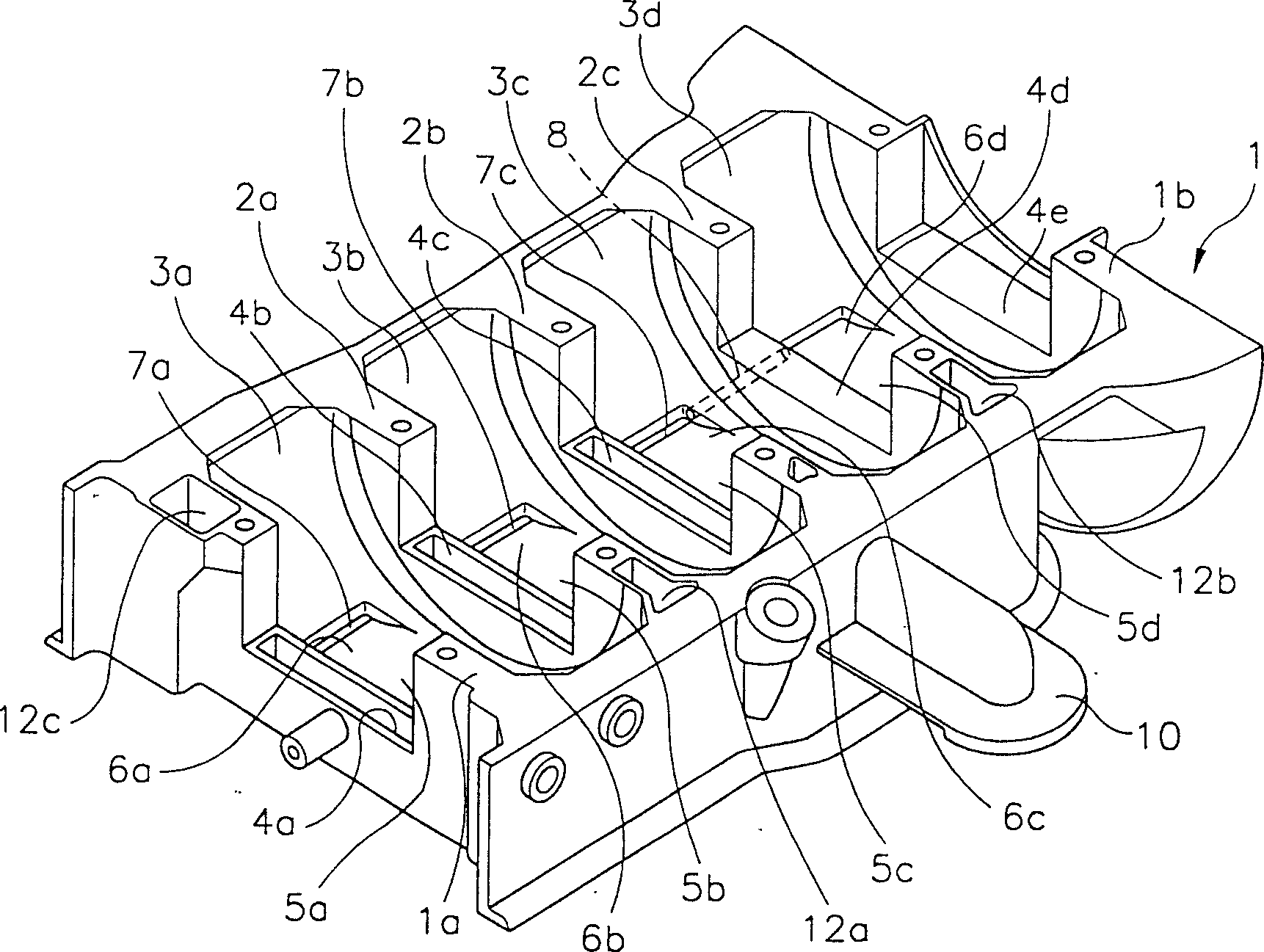
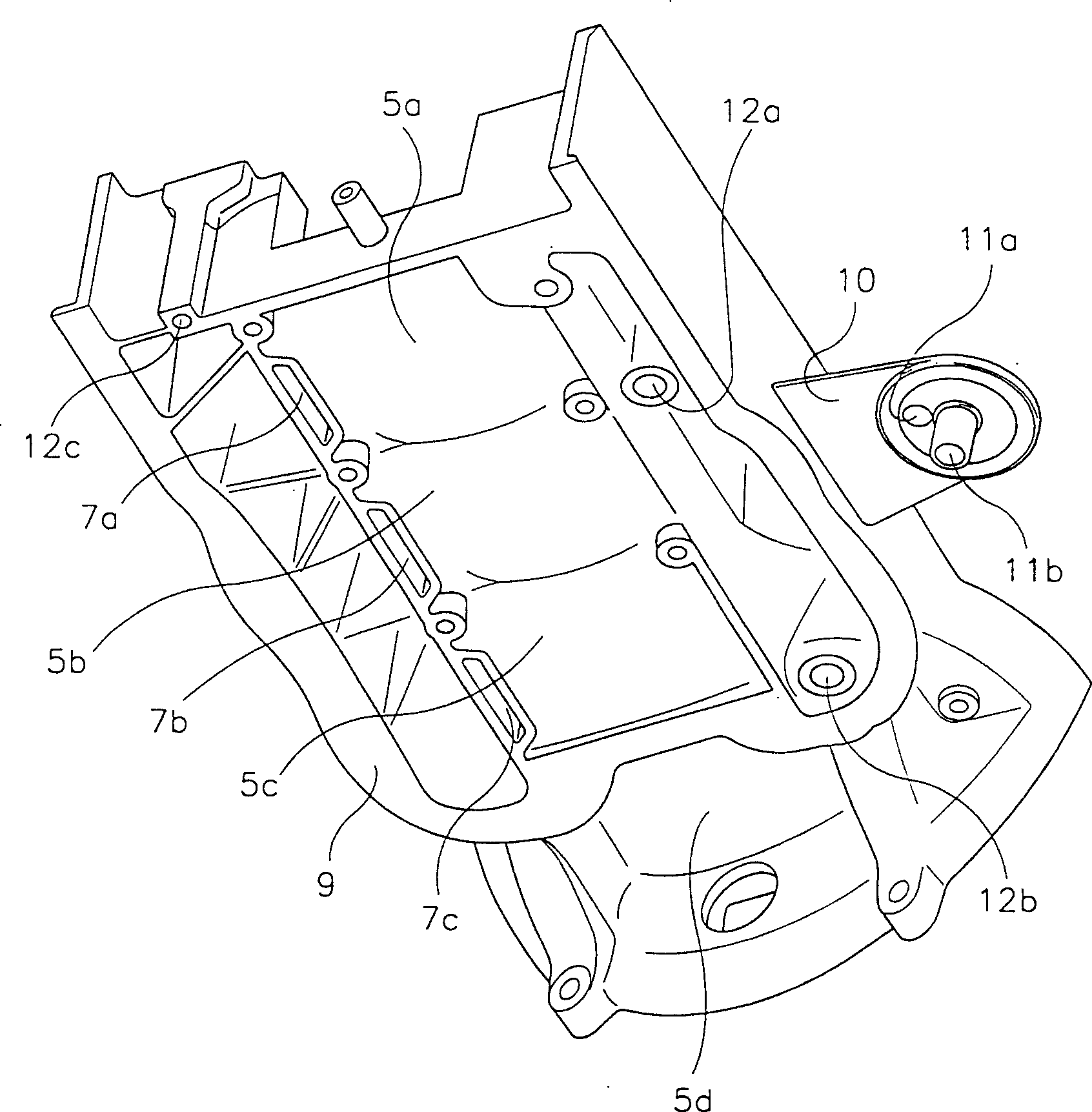
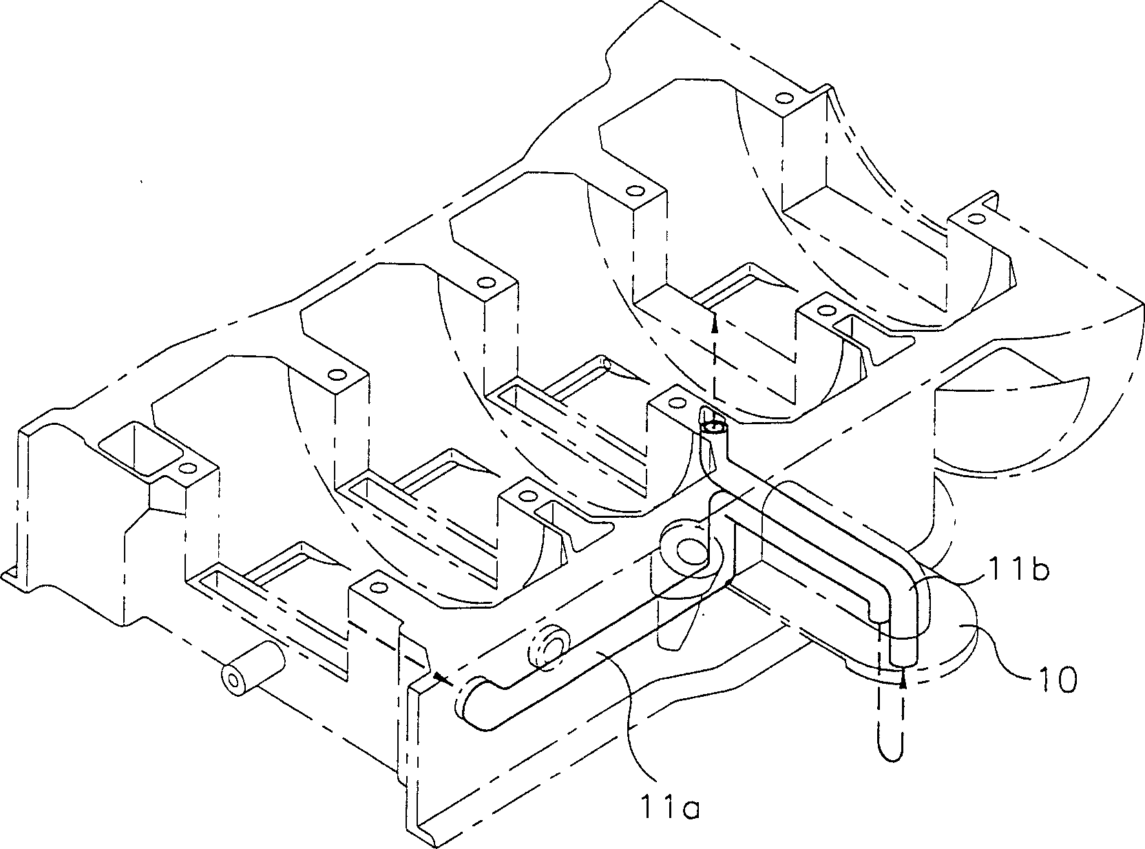
[0019] As shown in the figure, the stepped rack is constructed as follows. That is, a substantially elongated rectangular outer cylinder block 1 is formed in the casing of the four-cylinder engine. Inside the rectangular outer cylinder block 1, three partition walls 2a, 2b, and 2c are formed at equal distances, thereby forming four crankcases 3a, 3b, 3c, and 3d.

[0020] On the partition walls 2a, 2b and 2c and the front wall 1a and the rear wall 1b of the outer cylinder block 1, several elongated upward openings are formed, namely the main bearing installation parts 4a, 4b, 4c and 4e, which are used to install the main bearings to support crankshaft. Wherein, the outer end of the main bearing mounting portion 4e of the outer wall 1b is a part for connecting with the transmission input shaft, which is arcuate or almost arcuate, so that noise and vibration can be suppre...


PUM


Abstract

A ladder frame of an engine is disclosed, in which noise and vibrations are minimized, the installability of the oil filter is improved, and inclusion of air is reduced in the oil flowing from the cylinder head to the oil pan. Inside an elongate rectangular outer block, three partitioning walls are formed equidistantly, so as to form four crank chambers. The crank chambers of the outer block respectively have bottom faces which are not perforated or open but are completely closed. On the side parts of the bottom faces, there are respectively formed oil flow faces which gradually become deeper in the direction of the revolutions of the crankshaft. Among the oil flow faces, those of the first, second and third crank chambers have oil drain holes respectively at their ends. Thus the bottoms of the crank chambers are closed so as to close the space between the cylinder block and the oil pan, resulting in the reduction of the noise and vibrations.

Description

technical field [0001] The present invention relates to a stepped engine frame, more specifically, the stepped engine frame of the present invention can reduce noise and vibration, improve the installation performance of the oil filter, and prevent oil from flowing from the cylinder head to the oil pan. The middle prevents any air from entering the oil. Background technique [0002] A car engine usually consists of: a cylinder block with several cylinders for receiving the reciprocating motion of the piston; a cylinder head for mounting the camshaft driving the intake and discharge valves mounted on the upper to regulate the intake of air and the discharge of exhaust; and an oil pan mounted on the lower part of the cylinder block, which contains a certain amount of oil to lubricate the sliding parts of the engine [0003] The cylinder block is divided into a long stroke cylinder block and a short / half stroke cylinder block according to the length of the skirt member. [00...

Claims


Application Information

Patent Timeline
Patent Type & Authority Patents(China)
IPC IPC(8): F02F7/00F01M1/00F01M1/06F01M11/00F01M11/03
CPCF01M2011/0033F01M11/0004F01M2011/0079F01M11/03F02F7/00
Inventor 赵在万
Owner HYUNDAI MOTOR CO LTD
Why Eureka
Try Eureka