
Auto-locating confocal scan microscope with optical fibre

A confocal scanning and optical fiber scanning technology, applied in the field of optical fiber confocal scanning microscope, can solve the problems of limited spatial resolution, large error, long time, etc., and achieve the effects of strong anti-interference, small field of view, and convenient operation.

Inactive Publication Date: 2006-02-22
SHANGHAI INST OF OPTICS & FINE MECHANICS CHINESE ACAD OF SCI
View PDF0 Cites 0 Cited by
  • Summary
  • Abstract
  • Description
  • Claims
  • Application Information

AI Technical Summary

Problems solved by technology

(3) In terms of data acquisition, 3D scanning sampling is directly used to perform 3D image topology, which takes a long time for sampling and brings large errors
Its spatial resolution is limited by the sampling step size

Method used

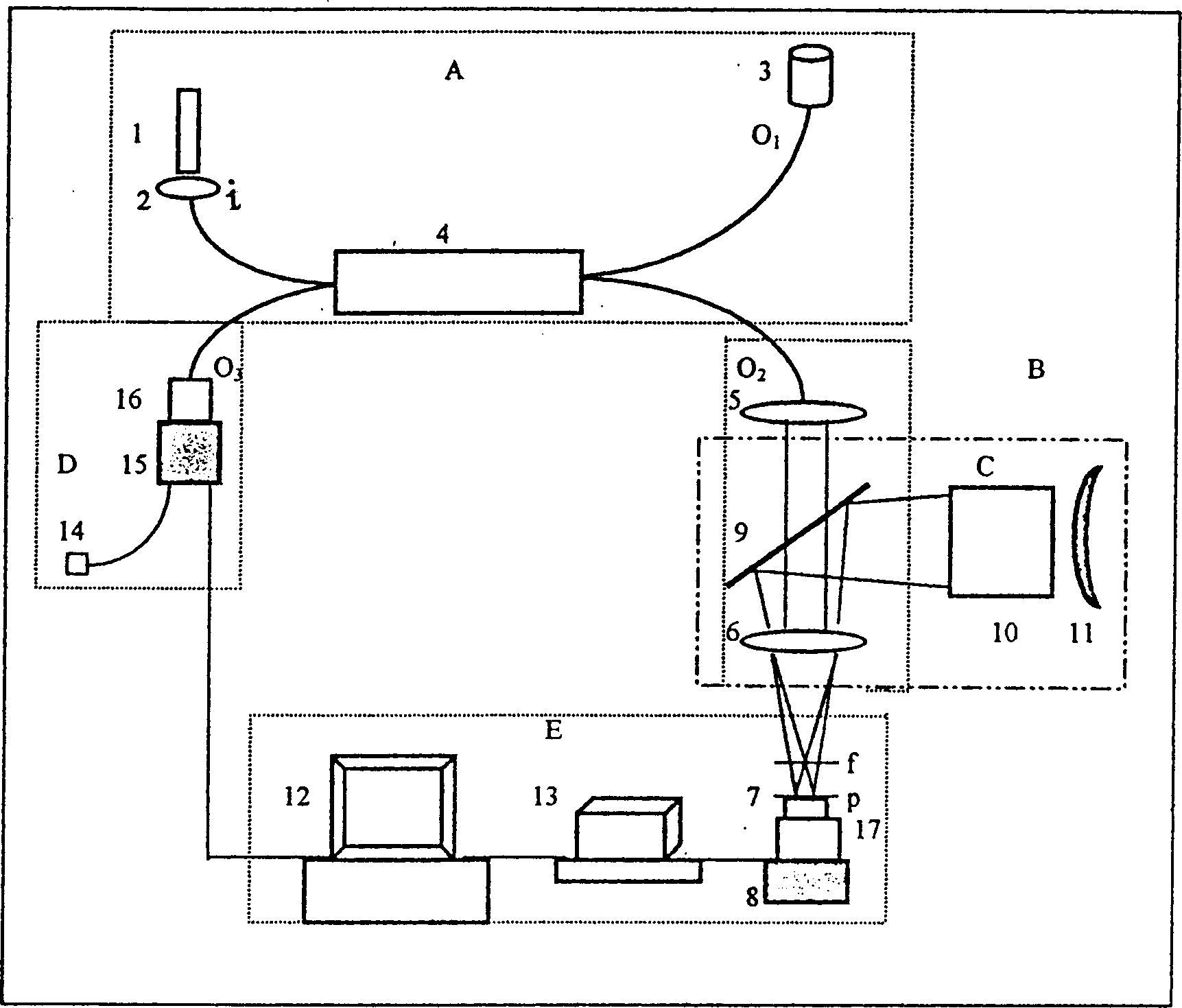

Image

  • Auto-locating confocal scan microscope with optical fibre
  • Auto-locating confocal scan microscope with optical fibre
  • Auto-locating confocal scan microscope with optical fibre

Examples


Embodiment 1

[0019] Such asfigure 1 In the structure shown, the laser 1 is a helium-neon laser, the detector 15 is a CCD detector (the image gap is 10 μm), the parameter of the sampling objective lens 6 is 40×, N(A) is 0.65, and the parameter of the beam collimator 5 is 4 ×, N(A) is 0.1, and the fiber coupler 4 is a single-mode fiber matched with the He-Ne laser beam. Its piezoelectric ceramic driver 8PZT moves with a resolution of 5nm. Test sample 7 is a blazed grating. Detect the shape and angle of the reticle. Its fineness is 1200 lines / mm, and its blaze angle is 22.3 degrees. The detection result of the present invention: the fineness is: 1200±50 lines / mm, and the detection data includes errors caused by grating manufacture and damage. Its blaze angle is 22.5±0.5 degrees. The present invention also detects the height of the reticle, and the result is 350±55nm. The test results showed that this grating was eliminated, and its surface was severely damaged. The cross-section of the ...

Embodiment 2

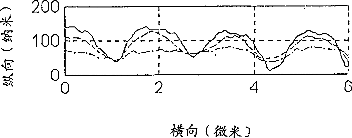
[0021] Still using the above-mentioned structure and parameters of each optical element, the tested sample 7 is an optical disc coated with a film layer, and its pre-groove is tested. The production data of the tested sample 7 are: the groove width is 0.4 μm, the groove spacing is 1.64±0.05 μm, and the groove height is 92±3 nm. The test result ( image 3 The solid line) is better than the state-of-the-art AFM ( image 3 Dashed line in the middle) and near-field scanning optical microscope ( image 3 The detection results of the dotted line). Depend on image 3 show.


PUM


Abstract

An auto-locating confocal scan microscope using optical fibre is composed of light beam input unit A, optical fibre scan unit B, measurement locating unit C alternative with B, probing-sampling unit D and control data acquisition and processing unit E. Said A, B, D and E constitute an optical fibre confocal scan microscope. Said A, B and C constitute a quasi-confocal small-view-field microscope. That is, it has both the microscan-tomographic imaging function and one-pass imaging function. It is suitable for examining 3D structure with nm depth and submicron width.

Description

Technical field: [0001] The invention is a self-positioning optical fiber confocal scanning microscope, which is suitable for three-dimensional structure detection with nanometer depth and submicron width. Background technique: [0002] In the 1990s, the technology of using single-mode fiber instead of pinhole appeared. Since then, confocal scanning microscopy technology using fiber optic devices has developed rapidly. There are two reasons. One is to directly input the laser into the optical fiber to avoid the vibration generated by the laser cooling system; the other is to simplify the structure and make the scanning confocal system more compact. But there is no big improvement in performance. In 1996, the patent applicant of the present invention also provided a fiber optic confocal scanning microscope based on a single-mode fiber coupler, which was published in the English version of "China Laser" magazine: Fiber Optic(A)lConfoc(A)l Sc(A)nning Microscope Using Single m...

Claims


Application Information

Patent Timeline
Patent Type & Authority Patents(China)
IPC IPC(8): G02B21/00
Inventor 王桂英杨莉松徐至展
Owner SHANGHAI INST OF OPTICS & FINE MECHANICS CHINESE ACAD OF SCI
Learn More