Optical fingerprint collector

A fingerprint collector and optical technology, which is applied in the fields of instruments, medical science, character and pattern recognition, etc., can solve the problems of optical fingerprint collectors such as difficulty in reducing the volume, prolonging the optical path, and increasing the size of the system, so as to reduce the size and avoid Interference, the effect of ensuring uniformity

Inactive Publication Date: 2006-03-22
苏州孔雀信天游电子有限公司
View PDF0 Cites 1 Cited by
  • Summary
  • Abstract
  • Description
  • Claims
  • Application Information

AI Technical Summary

Problems solved by technology

In the total reflection optical path, in order to reduce the size of the system, it is usually desirable to reduce the diameter of the first lens, however, if the diameter of the first lens is smaller than the fingerprint on the imaging surface, the lens assembly must be placed farther from the viewing surface , in order to make the edge of the captured fingerprint image clear, which will lengthen the optical path and increase the size of the system. This contradiction makes it difficult to reduce the size of the total reflection optical fingerprint collector, which limits its application.

Method used


Image

  • Optical fingerprint collector
  • Optical fingerprint collector

Examples


Embodiment 1

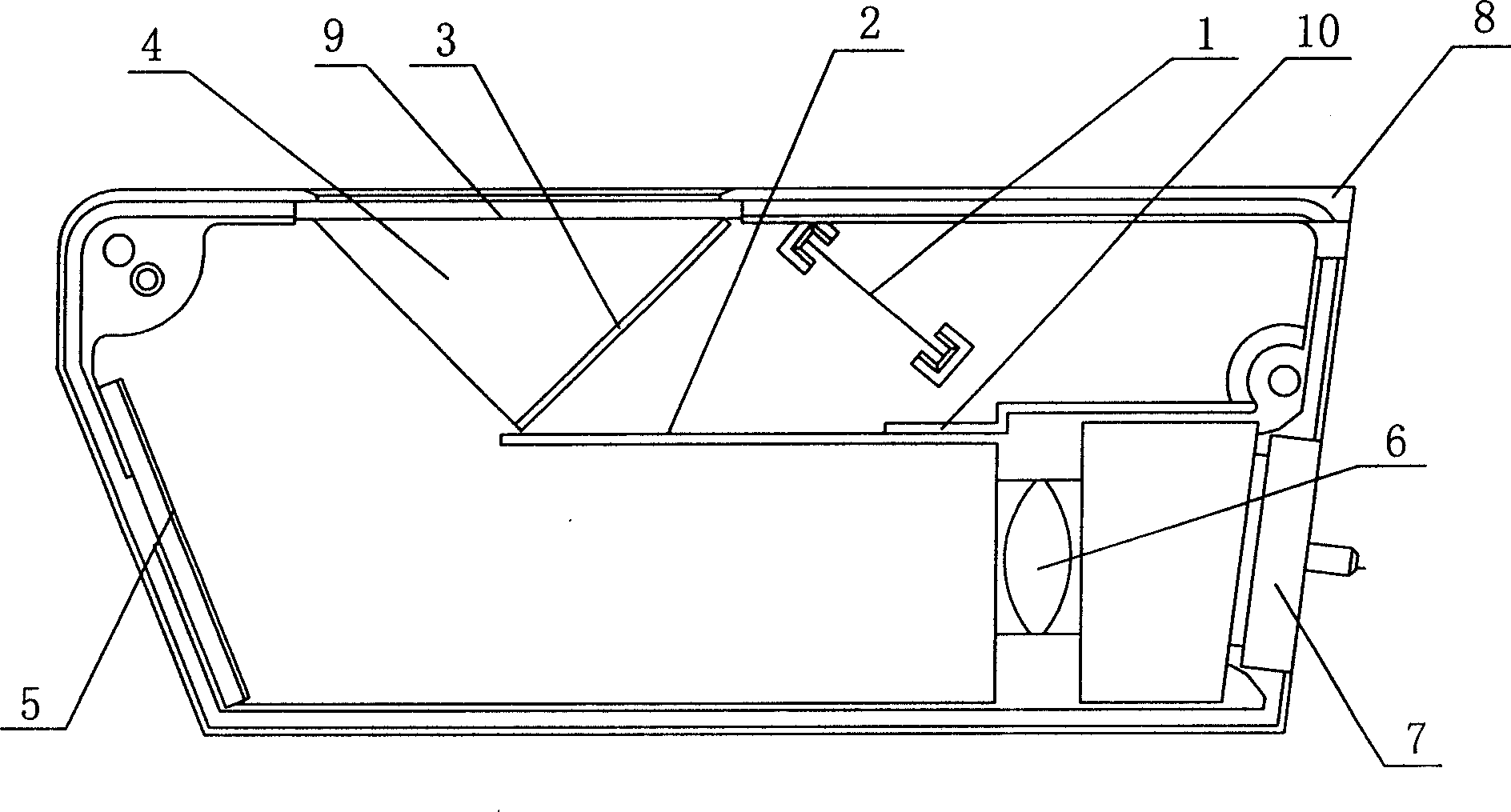
[0020] Embodiment one: see attached figure 2 As shown, an optical fingerprint collection instrument includes a light source 1, a light source reflector 2, a right-angle prism 4, an imaging reflector 5, an objective lens 6, an image sensor 7 and a housing 8, the right-angle prism 4 is an isosceles right-angle prism, Its imaging surface 9 is located at the opening of one side of the housing 8, the middle of the housing 8 is provided with a baffle 10, the baffle 10 is parallel to the imaging surface 9 of the prism 4, and the light source reflector 2 is fixedly connected to the baffle 10 , the angle between the normal direction of the imaging mirror 5 and the direction of the outgoing light is 157.5°.

[0021] In this embodiment, the image sensor 7 is a CMOS chip, and the angle between the CMOS chip and the optical axis of the objective lens is 83°.

Embodiment 2

[0022] Embodiment 2: An optical fingerprint collection instrument, comprising a light source 1, a light source reflector 2, a right-angle prism 4, an imaging reflector 5, an objective lens 6, an image sensor 7 and a housing 8, and the right-angle prism 4 is an isosceles right-angle prism , the imaging surface 9 is located at the opening of one side of the casing 8, the middle part of the casing 8 is provided with a baffle 10, the baffle 10 is parallel to the imaging surface 9 of the prism 4, and the light source reflector 2 is fixedly connected to the baffle 10 Above, the included angle between the normal direction of the imaging mirror and the outgoing light direction is 152°.

[0023] In this embodiment, the image sensor 7 is a CMOS chip, and the angle between the CMOS chip and the optical axis of the objective lens is 86°.

Embodiment 3

[0024] Embodiment 3: An optical fingerprint collection instrument, comprising a light source 1, a light source reflector 2, a right-angle prism 4, an imaging reflector 5, an objective lens 6, an image sensor 7 and a housing 8, and the right-angle prism 4 is an isosceles right-angle prism , the imaging surface 9 is located at the opening of one side of the casing 8, the middle part of the casing 8 is provided with a baffle 10, the baffle 10 is parallel to the imaging surface 9 of the prism 4, and the light source reflector 2 is fixedly connected to the baffle 10 Above, the angle between the normal direction of the imaging mirror and the direction of the outgoing light is 160°.

[0025] In this embodiment, the image sensor 7 is a CCD sensor, and the angle between the plane of the CCD sensor and the optical axis of the objective lens is 81°.


PUM


Abstract

Optical fingerprint collector is composed of light source, prism, lens, image sensor and case. The collector also includes reflector of light source and reflector of image. Angle between normal direction of reflector of image and direction of emergent light is within 150 degree to 165 degree. Under precondition of ensuring imaging sharpness, the invention reduces size of optical fingerprint collector so as to suit situation such as fingerprint lock needed of small size and sharpness.

Description

technical field [0001] The invention relates to a fingerprint image capture device, in particular to an optical fingerprint collector with a small volume. Background technique [0002] The fingerprint collector is the input device of the fingerprint identification system, which can be widely used in fingerprint locks, time attendance systems, mice, keyboards, mobile phones and other devices with fingerprint identification functions, and can also be used for fingerprint comparison and collection in public security systems. To improve the clarity of fingerprint recognition, an optical fingerprint collector is usually used. [0003] Existing optical fingerprint collectors have two types of optical paths: total reflection type and scattering type. The principle of the scattering optical path is that in the concave part of the fingerprint, the incident light will pass through the imaging surface, and in the convex part of the fingerprint, the incident lig...

Claims


Application Information

Patent Timeline
Patent Type & Authority Patents(China)
IPC IPC(8): G06K9/00A61B5/117A61B5/1172
Inventor 倪苏平陈伟元
Owner 苏州孔雀信天游电子有限公司
Why Eureka
Try Eureka