Micromechanical parts three-dimensional processing device

A processing device and micro-mechanical technology, applied in metal processing machinery parts, metal processing, metal processing equipment, etc., can solve the problems of inability to complete the nano-structure processing of complex macro parts of three-dimensional parts.

Inactive Publication Date: 2006-04-26
HARBIN INST OF TECH
View PDF0 Cites 1 Cited by
  • Summary
  • Abstract
  • Description
  • Claims
  • Application Information

AI Technical Summary

Problems solved by technology

However, these machine tools are powerless for the processing of nanoscale precision of tiny parts or the processing of nanostructures of macroscopic parts.
Scanning probe microscope processing is limited by the functional structure of the microscope itself. Although its nano-processing precision can reach the atomic level, it cannot complete the processing of three-dimensional parts and the processing of nanostructures of complex macro parts.

Method used


Image

  • Micromechanical parts three-dimensional processing device
  • Micromechanical parts three-dimensional processing device
  • Micromechanical parts three-dimensional processing device

Examples


Embodiment Construction

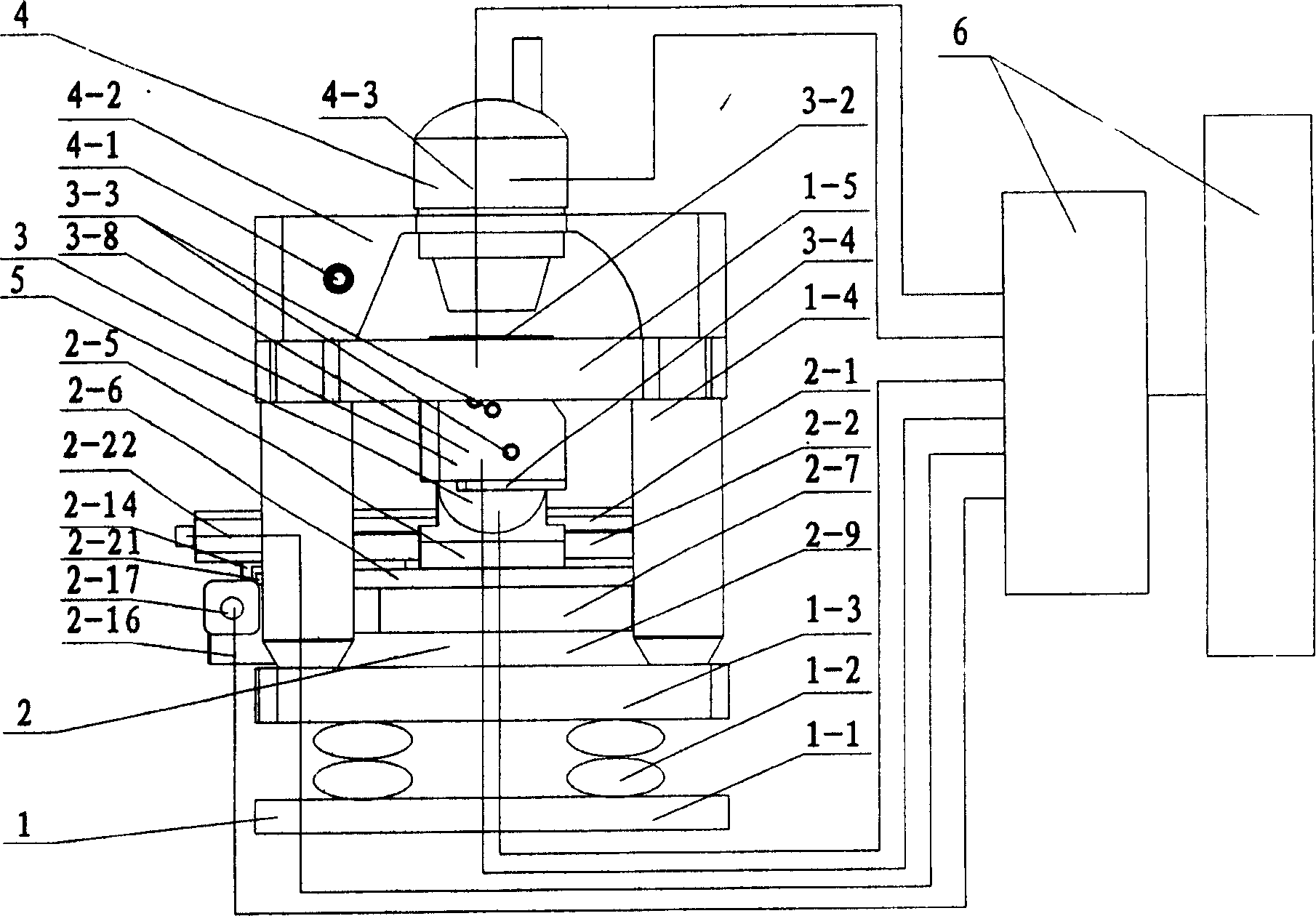
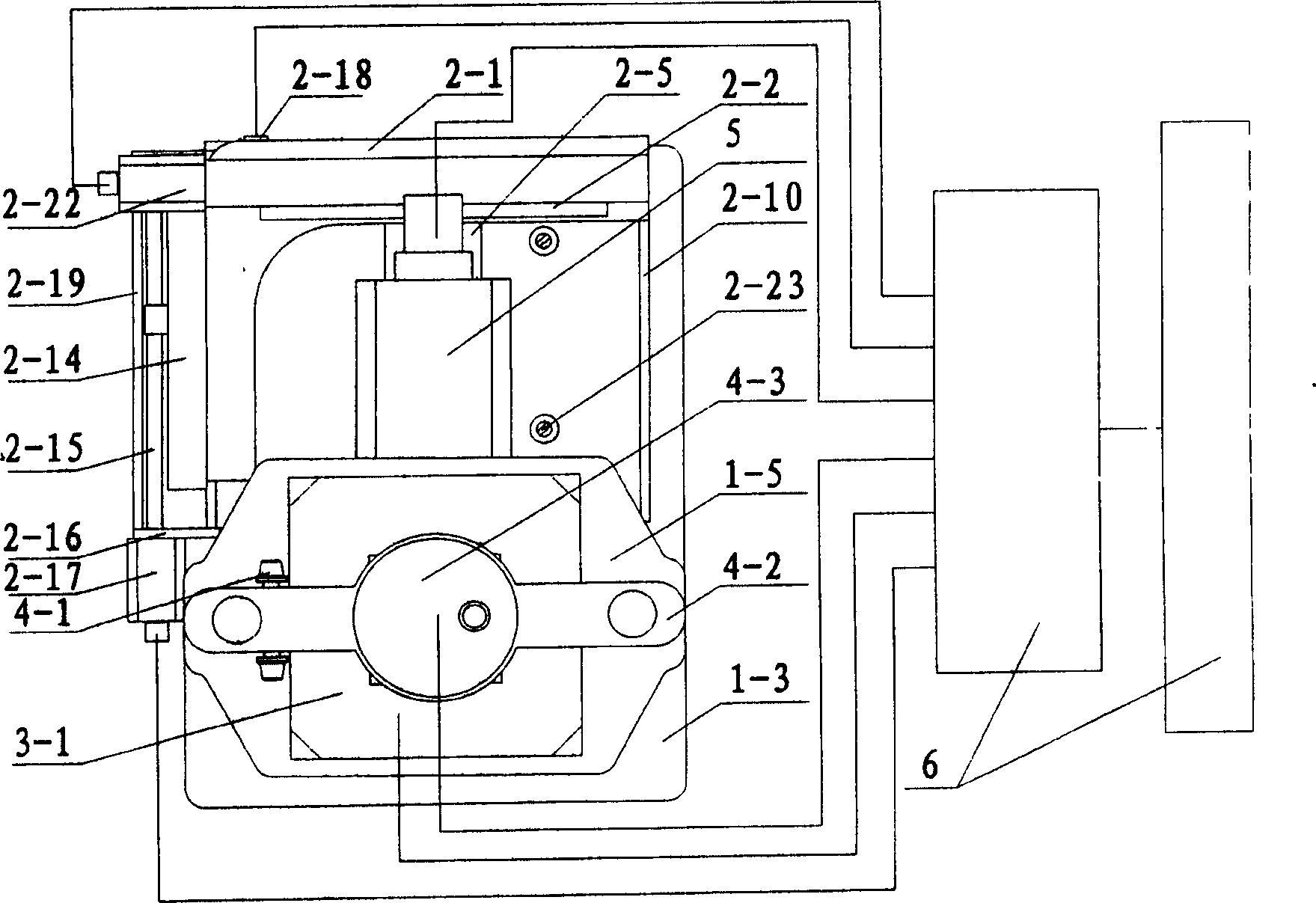
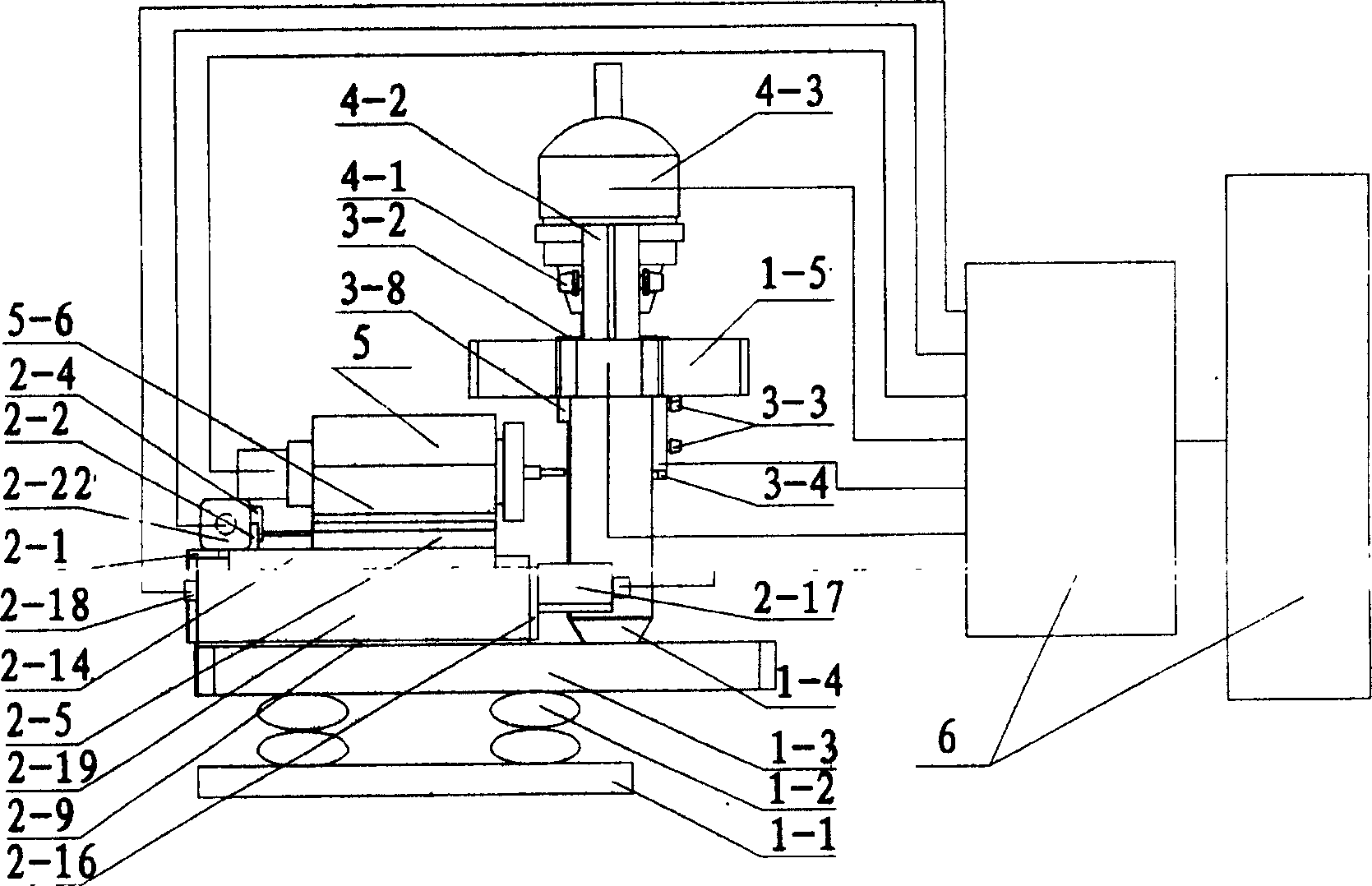
[0027]This embodiment includes a mechanical table body 1, a three-dimensional coarse motion table 2 arranged on the mechanical table body 1, a processing head part 3 and an optical system 4 are arranged on the mechanical table body 1, and a three-dimensional coarse motion table 2 is arranged on the mechanical table body 1. A spindle system 5 is provided, and the three-dimensional coarse motion table 2 , the processing head part 3 , the optical system 4 , and the spindle system 5 are all connected to a control system 6 . Wherein the mechanical table body 1 is the supporting body, the three-dimensional rough motion workbench 2 is placed flat on the table surface of the mechanical table body 1, the processing head part 3 is placed under the support beam 1-5 of the mechanical table body 1, and the optical system components 4 is installed above the bracket beams 1-5 of the mechanical table body 1, and the spindle system 5 is installed on the uppermost layer of the three-dimensional ...


PUM


Abstract

The utility model relates to a three-dimensional processing device for micromechanical parts, which belongs to a nano-processing device. The existing processing based on the scanning probe microscope is limited to the plane two-dimensional micro-pattern, and has not formed a complete set of processing mechanism and related technologies similar to ultra-precision diamond turning. The invention comprises a mechanical table body (1), a three-dimensional coarse motion workbench (2) arranged on the mechanical table body (1), and a processing head part (3) and an optical system ( 4), a spindle system (5) is provided on the three-dimensional coarse motion table (2), the three-dimensional coarse motion table (2), the processing head part (3), the optical system (4), the spindle system (5 ) are all connected with the control system (6). The product of the invention has the advantages of high precision and good effect.

Description

technical field [0001] The invention belongs to a nanometer processing device, in particular to a three-dimensional processing device for micromechanical parts. Background technique [0002] The term ultra-precision machining first appeared in the United States. In the 1960s, through the use of precision machine tools applicable at that time, single-point diamond turning tools were used to perform mirror cutting on aluminum alloys and oxygen-free copper, and starting from this, ultra-precision machining began to gradually develop as a new machining process stand up. The most representative one at that time was that in 1962, UNION CARDIE Company in the United States first developed an ultra-precision hemispherical lathe using porous graphite air bearings, successfully realized ultra-precision mirror turning, with a dimensional accuracy of ±0.6 μm and a rough surface. The thickness is Ra0.025μm, thus taking the first step in submicron or even nanoscale processing. Countries...

Claims


Application Information

Patent Timeline
Patent Type & Authority Patents(China)
IPC IPC(8): B23Q1/25B23Q5/00
Inventor 孙涛闫永达胡振江梁迎春张龙江董申
Owner HARBIN INST OF TECH
Why Eureka
Try Eureka