Probe cleaning device
A technology for probes and cleaning fluids, applied in measuring devices, measuring leads/probes, cleaning methods using liquids, etc., can solve problems such as confirmation troubles, difficulties in use and purchase, and insufficient contact, etc., to achieve high efficiency and reliability Effects of cleaning, miniaturization, and prevention of solvent cracks
- Summary
- Abstract
- Description
- Claims
- Application Information
AI Technical Summary
Problems solved by technology
Method used
Image

Examples
Embodiment 1
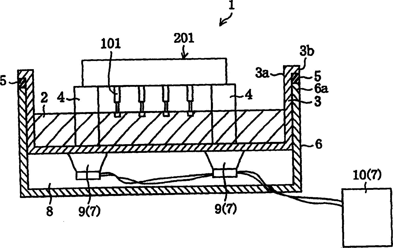
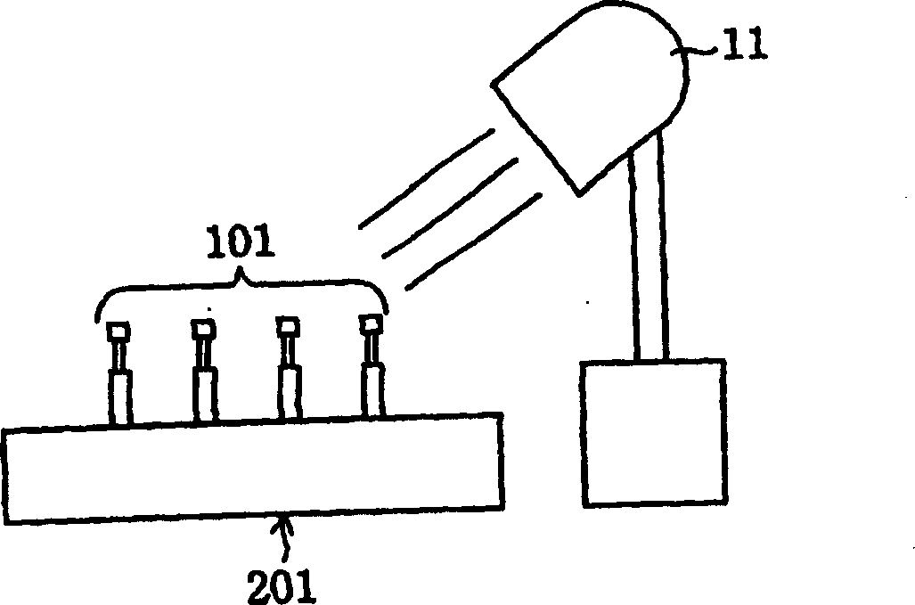
[0018] figure 1 It is a partial sectional view showing the structure of the probe cleaning device according to Embodiment 1 of the present invention, figure 2 is for figure 1 It is a front view of the ultraviolet irradiating device with different components used for cleaning the probe of the probe cleaning device shown.
[0019] Such as figure 1 As shown, the probe cleaning device 1 is to ultrasonically clean the stylus at the front ends of a plurality of probes (PP) 101 that are vertically fixed in a plug board (PB) 201 as a fixed member and facing downward. The clean cleaning device mainly includes: a bottomed box-shaped cleaning container 3 for holding the cleaning liquid 2; a plug-in connector that is arranged on the inner bottom of the cleaning container 3 and makes the probe 101 face downward; The pillar (support member) 4 that supports the plate 201 horizontally; the outer case 6 having the upper opening edge 6a that supports the outer edge 3b of the upper opening 3...
Embodiment 2
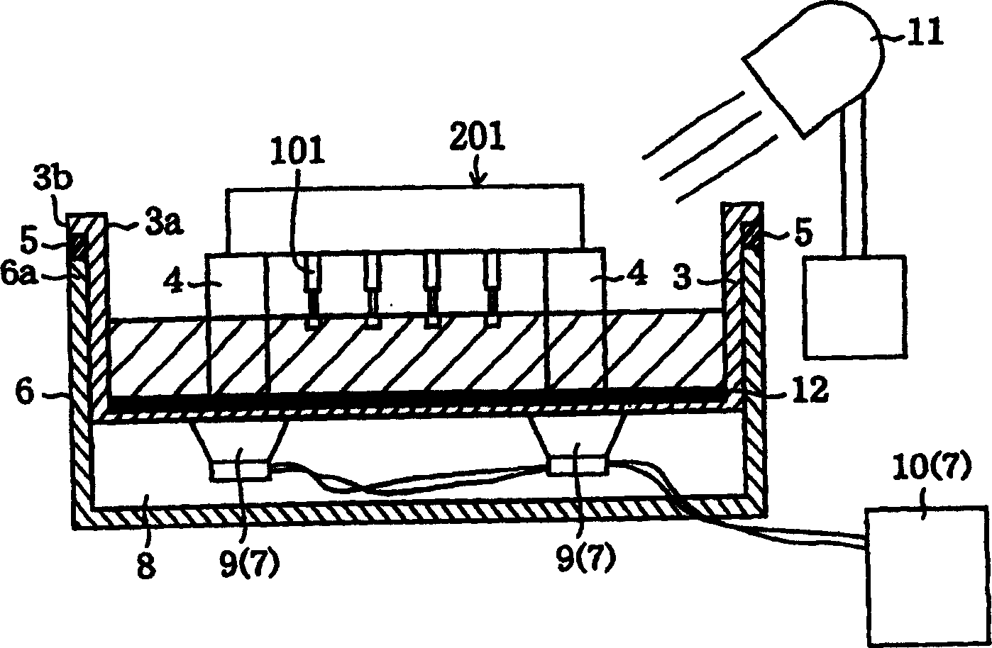
[0032] image 3 It is a partial sectional view showing the structure of the probe cleaning device according to the second embodiment of the present invention. Among the constituent members of the second embodiment, the same reference numerals are used for the parts common to the constituent members of the first embodiment, and descriptions of these parts are omitted.
[0033] The second embodiment is characterized in that a reflection mirror 12 is provided at the inner bottom of the cleaning container 3 to reflect ultraviolet light from the backlight 11 to the part of the contact needle of the probe 101 . In the present embodiment 2, the backlight 11 is arranged obliquely above the cleaning container 3, and it can irradiate ultraviolet rays to the reflector 12 in the cleaning container 3 from obliquely above the upper opening 3a of the cleaning container 3. In addition, when the inside of the cleaning container 3 is formed of a material that can transmit ultraviolet rays, the...
Embodiment 3
[0040] Figure 4 It is a partial cross-sectional view showing the structure of an automatic probe cleaning device according to Embodiment 3 of the present invention, Figure 5 is for illustration Figure 4 The flow chart showing the operation of the automatic probe cleaning device. Among the constituent members of the third embodiment, the same symbols are used for the parts common to the constituent members of the first embodiment, and the description of the parts is omitted.
[0041] The third embodiment is characterized in that the cleaning of the contact portion of the probe 101 by ultrasonic vibration is automated. That is, if Figure 4 As shown, an invisible light transmission area 3c such as ultraviolet rays is formed at the bottom of the cleaning container 3 of the automatic probe cleaning device 20, and the lower side of the invisible light transmission area 3c in the inner space 8 is equipped with an invisible light illumination function. The image recognition ca...
PUM
 Abstract
Description
Claims
Application Information
 - R&D
- Intellectual Property
- Life Sciences
- Materials
- Tech Scout
- Unparalleled Data Quality
- Higher Quality Content
- 60% Fewer Hallucinations
Browse by: Latest US Patents, China's latest patents, Technical Efficacy Thesaurus, Application Domain, Technology Topic, Popular Technical Reports.
© 2025 PatSnap. All rights reserved.Legal|Privacy policy|Modern Slavery Act Transparency Statement|Sitemap|About US| Contact US: help@patsnap.com