
Direct driving permanent magnet type magnetic resistance motor

A reluctance motor, permanent magnet technology, applied in the magnetic circuit shape/style/structure, electrical components, electromechanical devices, etc., can solve the problem of low magnetic circuit reluctance, increase the cost of the drive system, limit the motor performance volume ratio question

Inactive Publication Date: 2007-01-24
HARBIN INST OF TECH
View PDF2 Cites 1 Cited by
  • Summary
  • Abstract
  • Description
  • Claims
  • Application Information

AI Technical Summary

Problems solved by technology

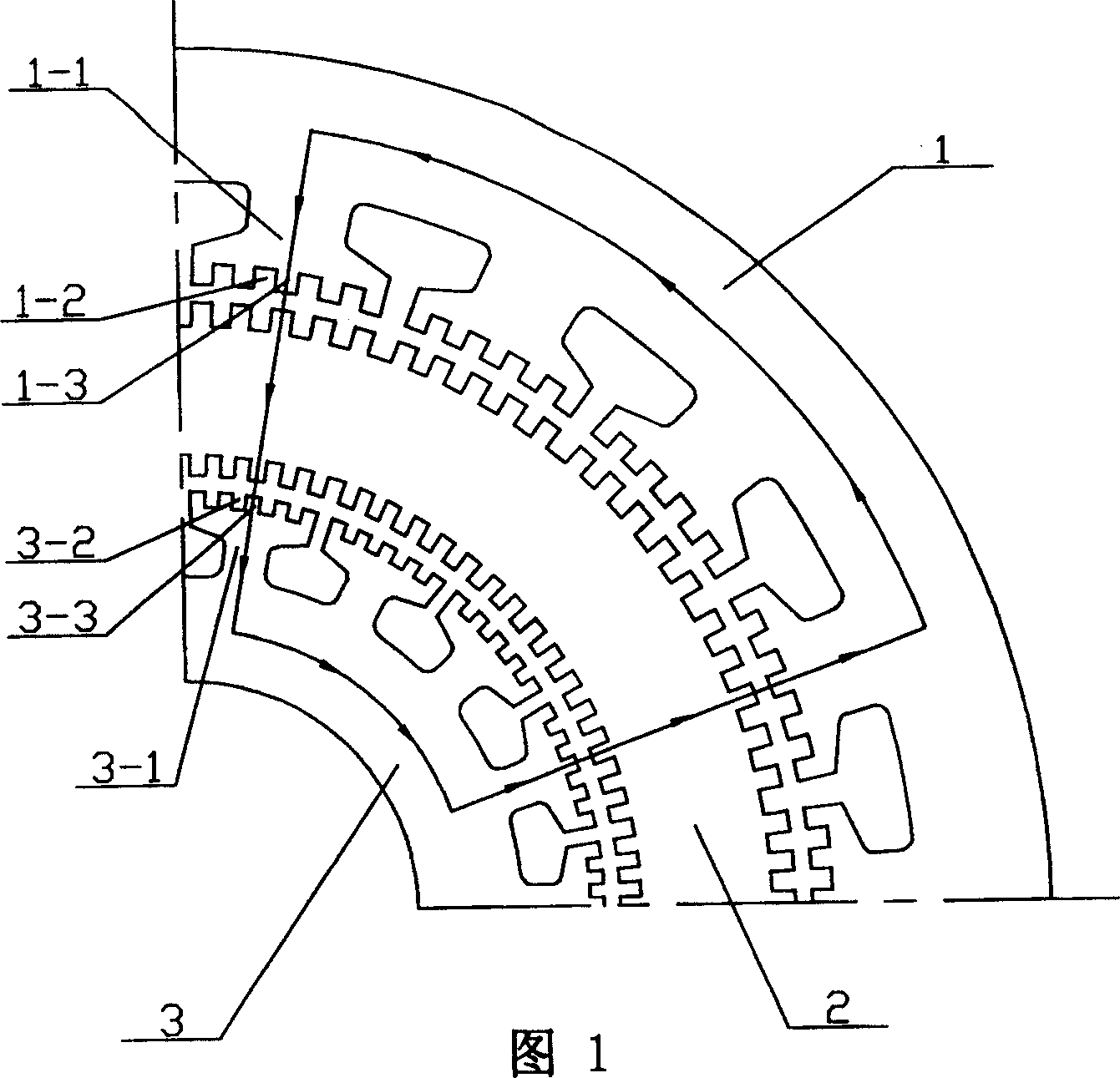
The magnetic flux passes through the thin-walled rotor 2 to the inner stator 3 in the radial direction from the outer stator 1. The magnetic circuit of the rotor is very short and the magnetic resistance of the magnetic circuit is very low. In this way, the magnetic flux generated by the unit ampere-turn of the motor is relatively high, and the motor has a high torque. , but there is some leakage magnetic flux at the slot 1-2 on the surface of the large pole 1-1 of the outer stator 1 and the slot 3-2 on the surface of the large pole 3-1 of the inner stator 3. Therefore, in order to obtain a large torque, Large excitation power is required, which limits the performance-to-volume ratio of the motor and increases the cost of the drive system

Method used


Image

  • Direct driving permanent magnet type magnetic resistance motor
  • Direct driving permanent magnet type magnetic resistance motor
  • Direct driving permanent magnet type magnetic resistance motor

Examples


specific Embodiment approach 1

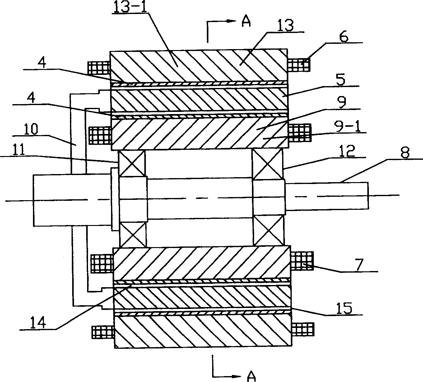
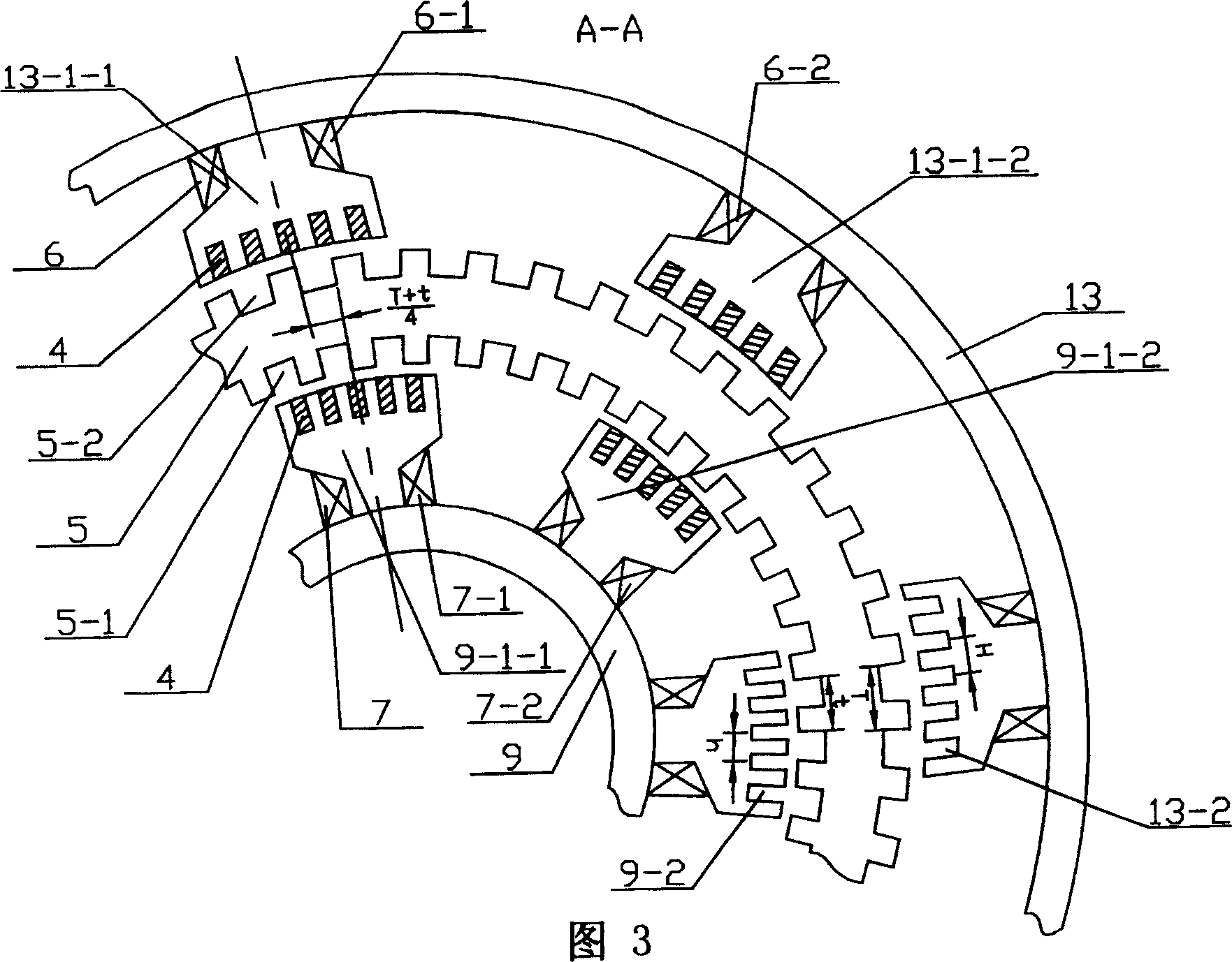
[0005] Specific implementation mode one: the following combination figure 2 , FIG. 3 and FIG. 4 illustrate the present invention in detail. It consists of rotor core 5, outer stator field winding 6, inner stator field winding 7, shaft 8, inner stator core 9, rotor cage 10, first bearing 11, second bearing 12, outer stator core 13 and permanent magnet 4 , the inner and outer circles of the rotor core 5 made of silicon steel sheets are respectively provided with a first tooth groove 5-1 and a second tooth groove 5-2, and the center line of the second tooth groove 5-2 and the first tooth groove The centerlines of 5-1 coincide, the first tooth slot 5-1 and the second tooth slot 5-2 are parallel to the axis line of the rotor core 5 and are evenly distributed on the circumference, and the outer circle of the rotor core 5 is aligned with the outer stator core 13 An outer air gap 15 is formed between the inner holes of the rotor core 5 and an inner air gap 14 is formed between the in...

specific Embodiment approach 2

[0006] Specific Embodiment 2: The present embodiment will be specifically described below with reference to FIG. 3 . The difference between this embodiment and Embodiment 1 is that the tooth pitch H of the third tooth slot 13-2 on the outer stator core 13 is two times the first tooth pitch T of the second tooth slot 5-2 on the outer circle of the rotor core 5. One-half of the pitch h of the fourth tooth slot 9-2 on the inner stator core 9 is half of the second pitch t of the first tooth slot 5-1 on the inner hole of the rotor core 5. The tooth pitch H and the tooth pitch h refer to the arc length.


PUM


Abstract

This invention discloses a direct drive permanent magnetic reluctance machine including rotor core, external stator excitation winding, inner stator excitation winding, sliaft, inner stator core, rotor keep frame, a bearing, bearing, and outer stator core among which, spline and spline are opened on internal and external cycles of the rotor core laminated by silicon steel sheets, permanent magnet is included, several uniform-distributed splines are opened on the surface of pole, splines on the surface of pole, strip magnet is iserted insplines and permanent magnet has a magnetic field along the tangent of, eliminating leackage in slot and increasing flux density of tooth.

Description

technical field [0001] The present invention relates to a direct drive reluctance motor. Background technique [0002] In the existing direct drive reluctance motor, as shown in FIG. 1 , the rotor 2 of the motor has a thin-walled cup-shaped structure and is placed between two concentric stators. By sequentially energizing the magnetic poles, the rotor 2 interacts with the stator to generate torque. Because the inner and outer stators interact with the rotor at the same time, the torque per unit core mass increases. The magnetic flux passes through the thin-walled rotor 2 to the inner stator 3 in the radial direction from the outer stator 1. The magnetic circuit of the rotor is very short and the magnetic resistance of the magnetic circuit is very low. In this way, the magnetic flux generated by the unit ampere-turn of the motor is relatively high, and the motor has a high torque. , but there is some leakage magnetic flux at the slot 1-2 on the surface of the large pole 1-1...

Claims


Application Information

Patent Timeline
Patent Type & Authority Patents(China)
IPC IPC(8): H02K37/02H02K1/17
Inventor 寇宝泉李立毅程树康李小鹏
Owner HARBIN INST OF TECH
Learn More