Robot torque motor with excitation regulating rotor

A technology of excitation regulation and permanent magnet motors, applied in the field of torque motors, can solve problems such as waste of magnetic performance, damage to the motor, and heat generation on the stator side

Inactive Publication Date: 2019-10-08
BEIJING INSTITUTE OF TECHNOLOGYGY
View PDF4 Cites 0 Cited by
  • Summary
  • Abstract
  • Description
  • Claims
  • Application Information

AI Technical Summary

Problems solved by technology

[0005] On the one hand, the rotor structure of the embedded permanent magnet synchronous motor in the prior art has a leakage magnetic circuit, which will cause part of the waste of the magnetic performance
[0006] On the other hand, the rotor side of the permanent magnet motor in the prior art is excited by permanent magnets, and the magnetic flux cannot be adjusted freely
According to the calculation formula of the output torque of the motor: T=C T ΦI a , where C T is the torque constant of the motor, Φ is the magnetic flux linked with the stator winding turns, I a It is the winding current. When running at low speed and high torque, the load capacity

Method used


Image

  • Robot torque motor with excitation regulating rotor
  • Robot torque motor with excitation regulating rotor
  • Robot torque motor with excitation regulating rotor

Examples


Embodiment 1

[0043] This embodiment provides an excitation adjustable rotor system for a torque motor.

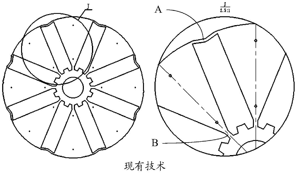
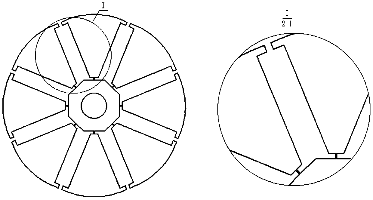
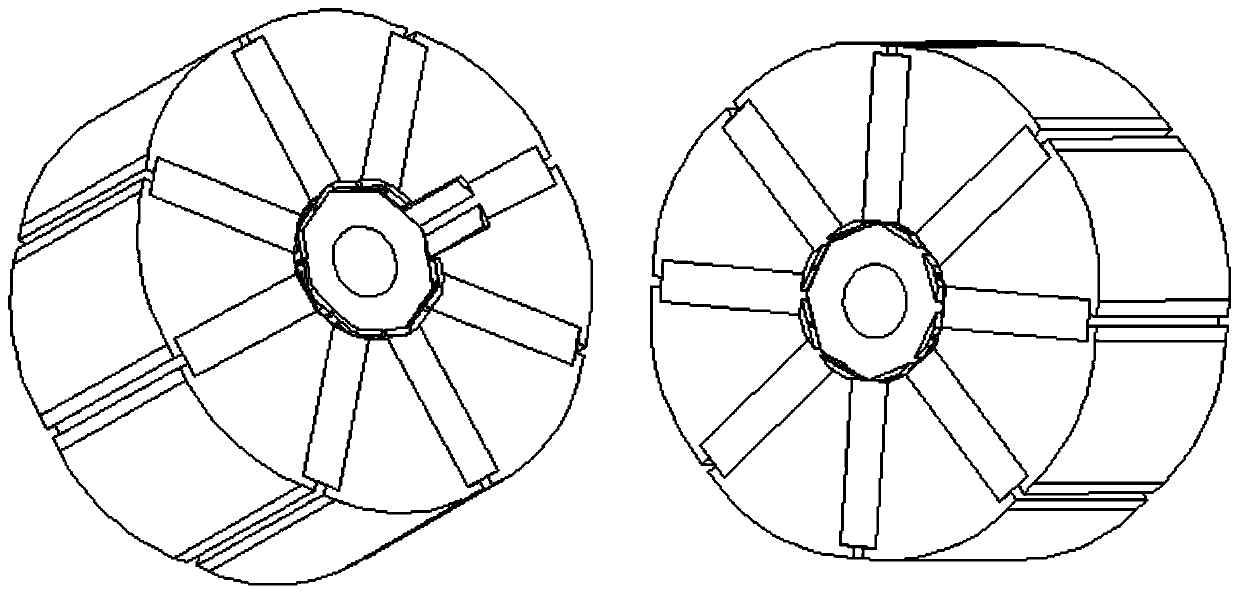
[0044] Such as Figure 2-4 As shown, the present invention passes through the figure 1 On the basis of the rotor iron core punching sheet of the technical scheme, the improved design of the leakage magnetic circuit is carried out to further reduce the magnetic flux leakage. figure 2 In the shown rotor core system according to the present invention, the outer magnetic isolation bridge is cut off, and the inner magnetic isolation bridge remains as a connecting bridge with a smaller size. As a result, the integrity of the rotor iron core stamping is guaranteed, and the leakage magnetic circuit is also greatly reduced.

[0045] exist figure 2 On the basis of the design of the rotor iron core stamping shown, an excitation adjustment device for adjusting the excitation is added to the connecting bridge in the rotor iron core.

[0046] Such as figure 2 As shown, the rotor system accord...

Embodiment 2

[0055] This embodiment provides a method for manufacturing a rotor system of a permanent magnet motor, comprising the following steps:

[0056] Provide rotor core punching;

[0057] Laminating the rotor iron core punching sheets to form a rotor iron core, the rotor iron core;

[0058] installing the dispersed winding in the magnetic isolation slot of the rotor core;

[0059] pouring thermal fluid insulating and shock-absorbing glue into the gap between the rotor core and the dispersed winding, so that the dispersed winding and rotor core form an integrated structure through the insulating and shock-absorbing glue;

[0060] Weld each dispersed winding for surface insulation treatment;

[0061] After connecting the distributed windings, they are connected end to end, and connected to an external circuit through a collector ring.

[0062] In a preferred embodiment, the dispersed windings are solid copper rods; the step of welding the dispersed windings is sequentially connecte...


PUM


Abstract

The invention provides a robot torque motor with an excitation regulating rotor. The rotor comprises a rotor core, an excitation regulating device and an insulating shock absorbing material. Accordingto the invention, the design of the leakage magnetic circuit is more perfect, and the magnetic separation effect is better; magnetic flux leakage can be completely eliminated; a rotor winding is usedto freely change the strength of a magnetic field, and the functions of flux enhancing and flux weakening are realized; problems in high speed and low speed operation of schemes in the prior art aresolved; perfused insulating damping rubber has an elastic damping effect, which can weaken radial electromagnetic force and torque fluctuation transmitted to a load through the rotor core and improvethe noise effect; the rotor winding and the iron core are integrated through glue filling; and the overall structural strength of the rotor can be ensured.

Description

technical field [0001] The invention relates to a torque motor for a humanoid robot, in particular to a robot torque motor with an excitation-adjustable rotor. Background technique [0002] Humanoid robots are no longer just a future technology that appears on the screen, and have long been widely sought after by various technological powers. Different from industrial robots, humanoid robots simulate human activities, and the motion conditions are more complex. Running at high speed and moving forward with a load, the requirements for the robot's drive motor are more stringent. [0003] The permanent magnet synchronous motor adopts the permanent magnet excitation method, which has significant performance advantages, and is currently the only choice to meet the humanoid robot drive. The continuous improvement of the performance requirements of high torque density motors has prompted engineering designers to pursue high-performance magnetic materials and technological change...

Claims


Application Information

Patent Timeline
IPC IPC(8): H02K21/04H02K15/03
CPCH02K15/03H02K21/042
Inventor 黄强张武孟兆平余张国陈学超高峻峣张弛陈进华
Owner BEIJING INSTITUTE OF TECHNOLOGYGY
Why Eureka
Try Eureka