High-efficiency motor with full-circumference magnetic flux polarized circumferential winding and new-energy electric vehicle

A magnetic pole and winding technology, which is applied in the field of high-efficiency motors and new energy electric vehicles, can solve the problems of reduced utilization of the stator winding magnetic field, multiple eddy current losses, resistive copper losses, magnetic flux leakage and high heat generation, etc., so as to eliminate the problem of heat generation , good regularity and consistency, saving copper and cost

Pending Publication Date: 2017-02-08
杨明
View PDF5 Cites 0 Cited by
  • Summary
  • Abstract
  • Description
  • Claims
  • Application Information

AI Technical Summary

Problems solved by technology

[0003] The motors of traditional technology mostly use chain winding or concentric winding, and the flux leakage and heat generated by the end of the winding are more, resulting in more eddy current loss and resistive copper loss. How to effectively reduce the loss caused by the end of the motor , has become an important technical issue restricting the efficiency of the motor
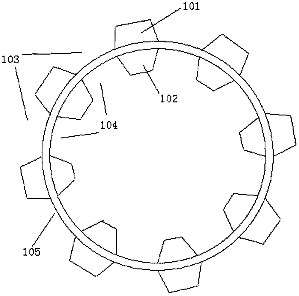
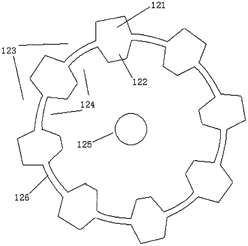
[0004] On the other hand, when the circumferential winding is used, for the stator core with single-direction single-circumference distributed magnetic poles, there are vacant positions between adjacent magnetic poles on the circumference, that is, the spacing between adjacent magnetic poles, The magnetic pole pitch is referred to as the magnetic pole pitch. Part of the magnetic field of the stator winding at the magnetic pole pitch is transmitted to the stator poles on both sides of the magnetic pole pitch in the form of a bending of the magnetic force line. Part of the magnetic field at the magnetic pole pitch leaks and diverges to the space around the magnetic pole pitch, which makes the magnetic field generated by the stator winding The utilization rate is reduced, and a large electromagnetic interference will be formed
[0005] Another important aspect is that at present, the motors used in new energy electric vehicles include: AC motors, permanent magnet motors, switched reluctance motors, etc. Generally, these motors still use the traditional motor structure with end windings. The above-mentioned shortcomings make the development of electric vehicles subject to the constraints of motor technology to a large extent; under the technical conditions of the existing vehicle-mounted power batteries, how to improve the efficiency and The power problem has become a key technical bottleneck restricting the development of electric vehicles. Therefore, it is urgent to develop new motors with high efficiency, energy saving and high reliability.

Method used


Image

  • High-efficiency motor with full-circumference magnetic flux polarized circumferential winding and new-energy electric vehicle
  • High-efficiency motor with full-circumference magnetic flux polarized circumferential winding and new-energy electric vehicle
  • High-efficiency motor with full-circumference magnetic flux polarized circumferential winding and new-energy electric vehicle

Examples


Embodiment 1

[0111] Such as Figure 5 As shown, it is a schematic diagram of the axial section of the stator of a full-circumference magnetic flux pole-splitting motor with single-phase circumferential winding, and its circumferential winding is the same as the above image 3 The same is shown for the circumferential windings, which are embedded in the slots between the circumferences 506 and 507 .

[0112] Such as Image 6 As shown, it is a schematic diagram of the axial section of the rotor of a full-circumference magnetic flux pole-splitting motor with single-phase circumferential winding. The stator core includes a yoke and a stator pole, and the yoke forms a continuous circumferential structure. The circumference of the yoke part has a slot cavity 505 capable of accommodating the stator windings. The stator poles are evenly distributed on both sides of the notch of the slot cavity, and the two sides of the slot are respectively connected to two opposite stator poles (such as the magn...

Embodiment 2

[0119] Such as Figure 8As shown, it is a sectional view of adjacent stator magnetic poles of a full-circumference magnetic flux split pole type circumferential winding motor. Two stator magnetic poles oriented 180° to each other are continuously distributed and alternately arranged on the entire circumference of the stator. The stator magnetic poles are now intercepted. A cross-sectional view of an adjacent stator pole of the core is used to illustrate the pole separation method of this embodiment.

[0120] In the figure, 142 is the cross-section of the circumferential winding, and 148 is a U-shaped magnetic core with the opening facing to the left: the U-shaped magnetic core includes a yoke 140, and two magnetic poles 143 and 144 are respectively connected on both sides of the notch to form a second magnetic pole. For a pair of magnetic poles facing one direction, when the circumferential winding is energized, the two magnetic poles 143 and 144 respectively exhibit different...

Embodiment 3

[0136] Such as Figure 10 As shown, it is a side sectional view of a single-phase circumferential winding with a full-circumference flux 90° polarized motor. Two U-shaped magnetic cores are alternately distributed on the stator circumference, and the bottom arcs of all U-shaped magnetic cores are A part of it is surrounded by a continuous groove structure capable of accommodating the circumferential winding. The circumferential winding 168 is placed in the groove, such as the stator core 173 (solid line in the figure). The core opening faces the left side as the first direction. Two magnetic poles connected in a circle form a pole pair 164; the stator core 174 (dotted line in the figure) facing the second direction has a magnetic core opening facing the upper side, and the two facing magnetic poles form an angle of 90° with each other, and the two sides of the notch are connected circumferentially. Two magnetic poles form a magnetic pole pair 166; similarly, the stator magneti...


PUM


Abstract

A motor with a full-circumference magnetic flux polarized three phase circumferential windings comprises three phase circumferential windings and six U-shaped stator magnetic poles which perform full-circumference magnetic flux polarization on the circumferential winding and have different orientations. A rotor shaft (200) is connected with rotor magnetic poles (202,203), (206,207), (212,213), (216,217), (222,223), (226,227) with a first orientation to a sixth orientation through rotor discs (201,211,221,231). The number of stator magnetic poles in a random orientation is same with that of the rotor magnetic poles in the orientation. Each phase circumferential winding controls two stator magnetic fields which performs polarization on the full circumference and in two orientations. The three phase circumferential windings (204,214,224) respectively control three phase stator and rotor magnetic fields which are at 120 DEG electric angle to one another. An electronic control system controls current of the three phase circumferential windings through testing the position of a rotor and is used as a motor or a power generator. The motor has advantages of small amount of magnetic flux leakage and high efficiency.

Description

technical field [0001] The invention belongs to the technical field of motors, and in particular relates to a high-efficiency motor and a new energy electric vehicle with full-circumference magnetic flux pole-splitting circumferential windings. Background technique [0002] The motor is a very important electromechanical conversion device, and its energy conversion efficiency is a particularly important technical indicator. The essence of improving efficiency is to reduce the loss of the motor as much as possible. [0003] The motors of traditional technology mostly use chain winding or concentric winding, and the flux leakage and heat generated by the end of the winding are more, resulting in more eddy current loss and resistive copper loss. How to effectively reduce the loss caused by the end of the motor , has become an important technical issue restricting the efficiency of the motor. [0004] On the other hand, when the circumferential winding is used, for the stator ...

Claims


Application Information

Patent Timeline
Patent Type & Authority Applications(China)
IPC IPC(8): H02K3/28H02K1/14H02K1/24
CPCH02K1/146H02K1/24H02K3/28
Inventor 杨明
Owner 杨明
Why Eureka
Try Eureka