Stabilizer of gas drill horizontal well

A technology for horizontal wells and centralizers, applied in the direction of drilling equipment, drill pipes, drill pipes, etc., which can solve the problems of hindering the movement of cuttings, difficult migration, and inability to be broken again, so as to achieve uniform flow rate, eliminate low-velocity areas, and Lower friction effect

Inactive Publication Date: 2007-05-30
SOUTHWEST PETROLEUM UNIV
View PDF3 Cites 2 Cited by
  • Summary
  • Abstract
  • Description
  • Claims
  • Application Information

AI Technical Summary

Problems solved by technology

2. The larger particle cuttings produced after the drill bit is broken are neither easy to be transported nor broken again. They first stay on the downhole wall and become an obstacle to the migration of other cuttings.
4. The cuttings lack the power to re-accelerate and impact other cuttings particles during the migration process.

Method used


Image

  • Stabilizer of gas drill horizontal well
  • Stabilizer of gas drill horizontal well

Examples


Embodiment Construction

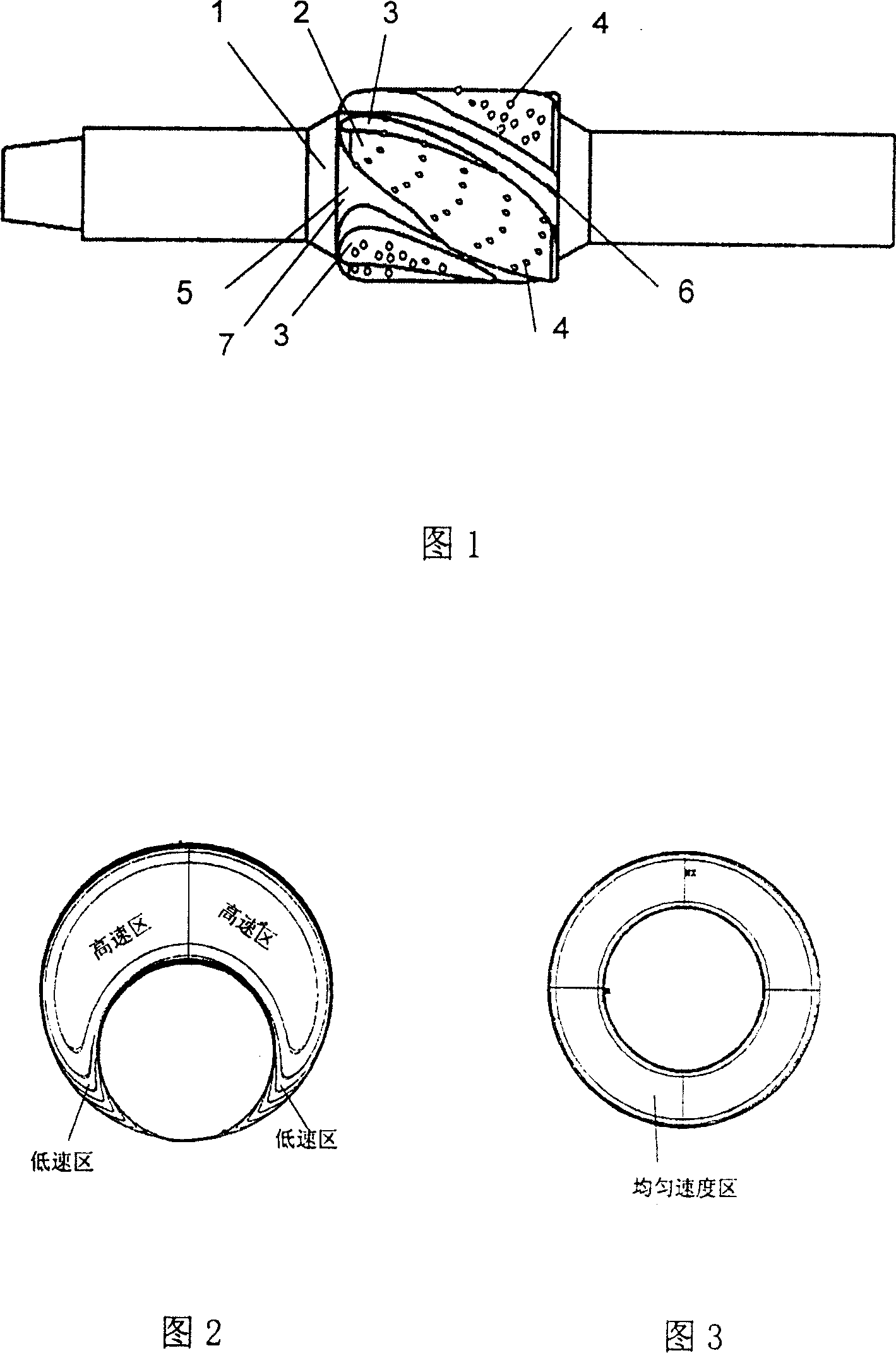
[0015] Referring to Fig. 1, a drilling tool centralizer for gas drilling horizontal wells is mainly composed of a centralizer body 1, a diversion groove 7, a centralizing strip 2, etc., and is characterized in that the diversion groove 7 is helical and has Wide inlet channel 5, narrow outlet channel 6, and the raised helical centralizing strip 2 sandwiched between the diversion grooves have a helix angle of 18° to 25°, and the centralizing strip has a cuttings introduction groove 3 , the width of the cuttings import groove corresponding to the wide inlet flow path and the narrow outlet flow path of the diversion groove gradually decreases, and the surface of the cuttings introduction groove 3 and the surface of the centralizing strip 2 are inlaid with cemented carbide teeth 4 .

[0016] Referring to Fig. 2 and Fig. 3, the centralizer has the function of lifting and straightening the drill string, reducing or even eliminating the flow field in the low-velocity zone of the eccent...


PUM


Abstract

A centralizer of drilling rod for the pneumatic drilling of horizontal well is composed of a main body, the spiral flow guide slots with wide inlet and narrow outlet, and spiral centralizing strips with rock bit leading-in slots. The hard alloy teeth are inlaid on the surfaces of said spiral flow guide slots and spiral centralizing strips.

Description

technical field [0001] The invention relates to a special drilling tool centralizer when drilling a horizontal well using gas as a circulating medium. The centralizer is also suitable for drilling horizontal wells using fluid as circulating medium. technical background [0002] In the drilling of high-inclination wells, horizontal wells, extended-reach wells, branch wells and other complex-structured wells, due to the large-angle inclination of the well section, even horizontal, it is difficult to move cuttings, and cuttings stay on the lower well wall. The phenomenon of aggregation and bed formation will eventually lead to the sticking of the drill string, and even the inability to continue drilling. [0003] The main reasons for cuttings migration difficulties are as follows: 1. Due to gravity, the drill string lies on the lower well wall to form an eccentric annulus, and the eccentric annulus causes a low velocity zone at the lower well wall. 2. The larger particle cutt...

Claims


Application Information

Patent Timeline
Patent Type & Authority Patents(China)
IPC IPC(8): E21B17/10
Inventor 孟英峰练章华梁红吴仕荣李永杰陈刚刘硕琼雷桐
Owner SOUTHWEST PETROLEUM UNIV
Why Eureka
Try Eureka