
Vaporization equipment for material sublimation

A technology of evaporation device and heating device, which is used in devices for measuring time interval, vacuum evaporation coating, metal material coating process, etc.

Inactive Publication Date: 2007-08-22
APPLIED MATERIALS GMBH & CO KG
View PDF5 Cites 1 Cited by
  • Summary
  • Abstract
  • Description
  • Claims
  • Application Information

AI Technical Summary

Problems solved by technology

[0004] Usually, there is the problem that the evaporation device must be able to accommodate a relatively large amount of material to be evaporated, so that the coating equipment can be operated continuously for as long as possible

Method used


Image

  • Vaporization equipment for material sublimation
  • Vaporization equipment for material sublimation
  • Vaporization equipment for material sublimation

Examples


Embodiment Construction

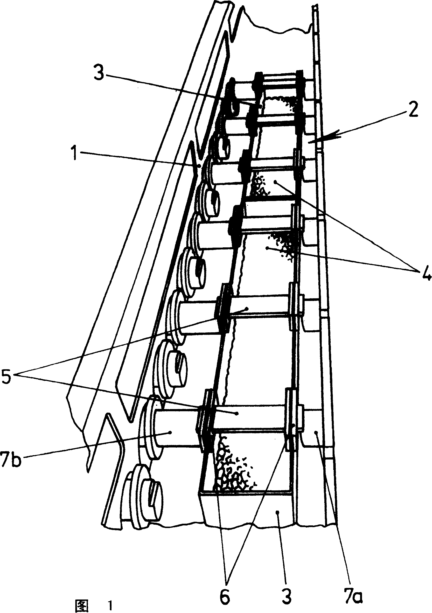
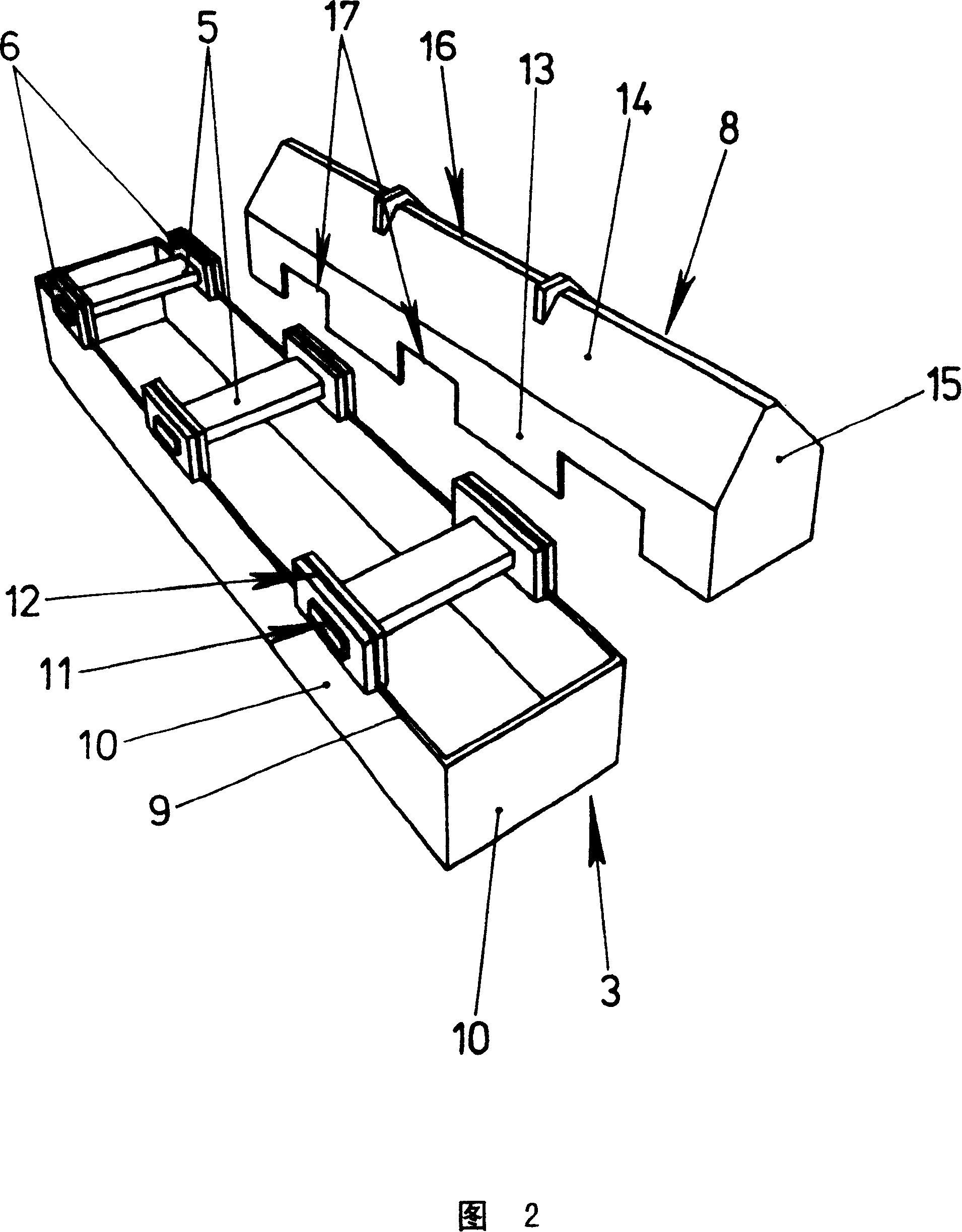
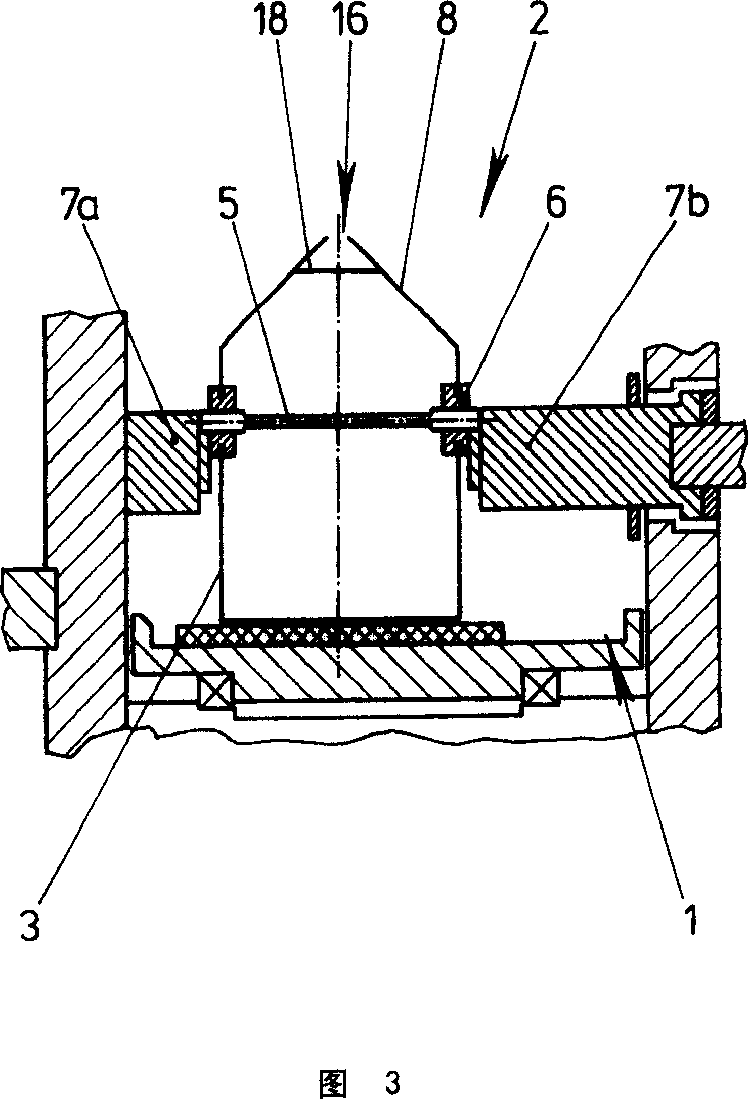
[0018] See Figure 1 first. One can see the vapor deposition chambers 1 of a coating plant, which are distributed in the form of wells over the width of the plant. By means of rollers, not shown, the film web to be coated can be passed through the vapor deposition chamber opening. In the evaporation chamber 1 there is an evaporation device 2, which consists of two elongated grooves 3, the short sides of which are in contact with each other. In the tank 3 there is material 4 to be evaporated, in this case zinc sulphide granules, which are introduced into the tank as bulk material. Three heating rods 5 are arranged on each slot 3 and are arranged at equal distances from one another. They are fixed by the support ring 6, wherein the two ends of the heating rod 5 protrude out of the groove 3 and can be connected with the contact rod 7 protruding from the wall of the evaporation chamber. The slot 3 is closed by means of a cover, which is not shown in this figure but is shown in d...


PUM


Abstract

The invention relates to a vaporizing arrangement. It preferably should be utilized in vacuum coating systems. The vaporizing arrangement comprises a two-part housing, namely a pan ( 3 ) and an associated lid ( 8 ), which is provided with the exit slot ( 16 ) for the material to be vaporized. Extending transversely above the pan ( 3 ) are several heating rods ( 5 ) which can be contacted on the outside and the radiant output of which heats the material to be vaporized, for example zinc sulfide, and causes it to vaporize. The arrangement is relatively simply constructed, can be easily disassembled, cleaned, and reassembled and can, if several arrangements of this type are combined, also be used for the uniform coating of very wide films.

Description

technical field [0001] The present invention relates to evaporation devices for sublimation materials. Background technique [0002] Such an evaporation device is described in GB2339800A. The evaporator is used, for example, in vacuum coating plants to apply a thin layer of material such as zinc sulfide to the film. Such a vacuum coating system comprises an evacuable container in which there is an elongated shaft through which the film or film web to be coated is conveyed by means of various rollers. The evaporating device is provided in the shaft so that the vapor from the evaporating device can be deposited on the film in a thin layer. [0003] The evaporating device mainly consists of a long tank for containing the material to be evaporated and a heating device. GB2339800 specifies in particular that the heating means consist of radiant heaters which are arranged below the tank and heat the bottom of the tank and thus indirectly heat the material to be evaporated, ther...

Claims


Application Information

Patent Timeline
Patent Type & Authority Patents(China)
IPC IPC(8): C23C14/24C23C14/26C23C14/28
CPCC23C14/243C23C14/28G06C1/00G04F7/065
Inventor G·克勒姆J·赫佐格H·-G·洛特兹
Owner APPLIED MATERIALS GMBH & CO KG
Learn More