
Computerized digital control system of laser metal surface enhanced processor

A metal surface strengthening, numerical control system technology, applied in computer control, general control system, control/adjustment system, etc., can solve the problems of lack of support means for laser strengthening treatment, poor operation and maintenance performance, complicated and cumbersome control circuit connection, etc. , to achieve the effect of friendly operation interface, improve production efficiency and processing quality, easy to drive and control

Inactive Publication Date: 2002-03-13
SHANGHAI UNIV OF ENG SCI
View PDF0 Cites 7 Cited by
  • Summary
  • Abstract
  • Description
  • Claims
  • Application Information

AI Technical Summary

Problems solved by technology

In order to ensure the need of real-time control, the control program of the special system is often developed in assembly language and DOS environment, so the redevelopment of the system is difficult
These systems also lack support for the process test of laser strengthening treatment
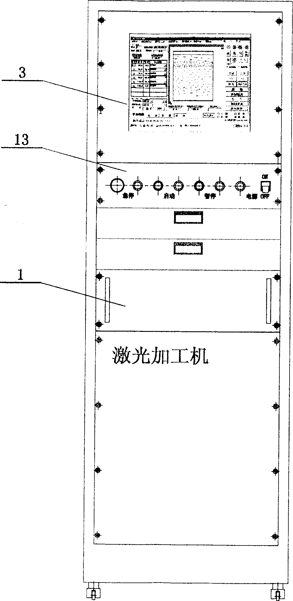
In addition, these systems all rely on the operation panel as the interface for human-computer interaction, requiring a large number of operation buttons, switches and indicator lights, the connection of the control circuit is complicated and cumbersome, and the operation and maintenance performance is poor.

Method used


Image

  • Computerized digital control system of laser metal surface enhanced processor
  • Computerized digital control system of laser metal surface enhanced processor
  • Computerized digital control system of laser metal surface enhanced processor

Examples


Embodiment Construction

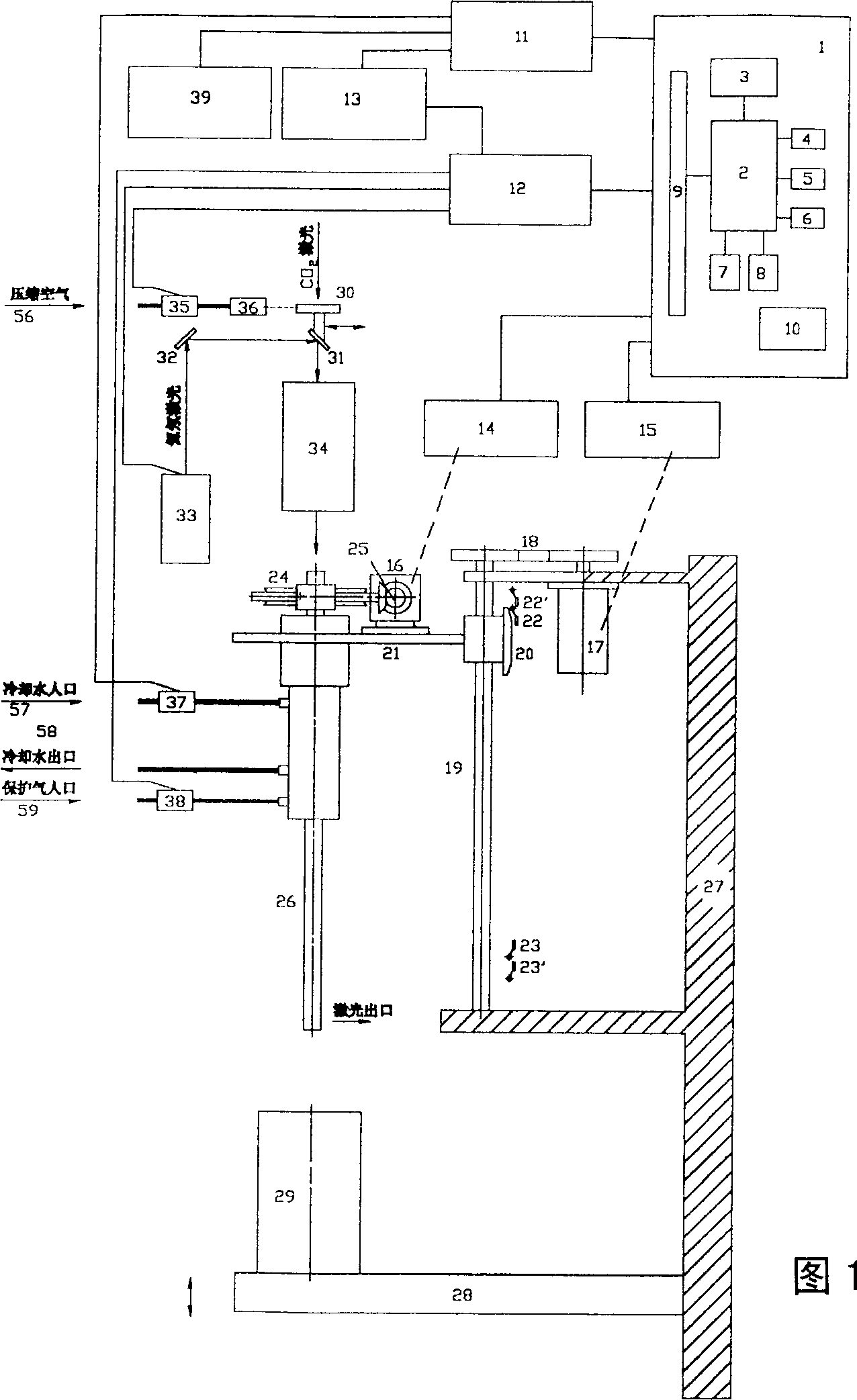
[0050] Fig. 1 is a schematic diagram of the system structure of the present invention.

[0051]The Z-axis stepping motor 17 installed on the bed of the machine tool drives the lifting platform 21 to move up and down through the transmission gear 18 and the transmission screw 19. The lifting platform is equipped with a C-axis stepping motor 16, a main shaft part 26 and a main shaft transmission part... ...A pair of bevel gears 25 and a pair of worm gears 24, the motor 16 drives the main shaft 26 to rotate through the bevel gears 25 and the worm gears 24. The control program puts forward the walking control requirements to the stepping motion control card (hereinafter referred to as the stepping card) 9 in the form of walking commands, and the stepping card 9 sends out the stepping pulse signal PCW respectively as required C 、DCCW C and PCW Z 、DCCW Z to the stepper motor drivers 14 and 15, the drivers then generate the three-phase drive pulse signals required by the three-pha...


PUM


Abstract

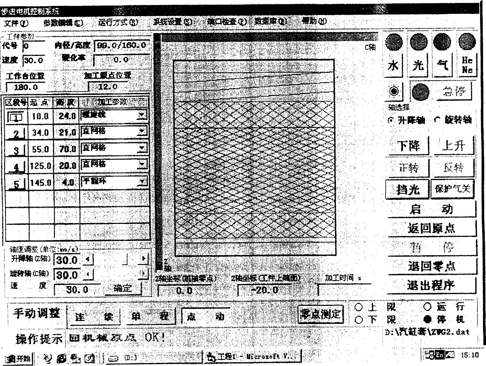
In the laser metal surface enhancing processor, each of the two driving shafts is driven by a stepped motor and the computerized control system sends out motor stepping pulse via the control card according to the reinforced locus requirement to complete the motion control in two directions. The operation is performed via screen control to replace large amount of buttons and switches resulting in simple control circuit and operation panel and friendly operation interface. The control program is one under Windows98 environment and has user accessed machining locus parameters and partial machinetool structure parameters, and all these makes the system is programming-free and reconfigurable. In addition, the operation interface is programmable and the system is opened.

Description

Technical field: [0001] The invention relates to a laser processing machine, and is a computer numerical control system for a laser metal surface strengthening treatment machine, in particular a computer numerical control system for a laser surface strengthening treatment machine for the inner wall of a cylinder body (sleeve). Background technique: [0002] Most of the laser surface strengthening treatment equipment adopts the method of workpiece movement and laser beam fixation for laser surface strengthening treatment, so it is more complicated to control the ever-changing workpiece; and the control system mostly uses a dedicated numerical control system, these systems are based on the environment of numerical control programs, and users need Use the NC language provided by the system to perform a series of operations such as NC program compilation, input, editing, maintenance, and debugging for various processing requirements. In order to ensure the needs of real-time con...

Claims


Application Information

Patent Timeline
Patent Type & Authority Applications(China)
IPC IPC(8): C21D10/00G05B15/02
Inventor 陈昌锡周建鹏张光钧曹永上
Owner SHANGHAI UNIV OF ENG SCI
Learn More