Supercharge Your Innovation With Domain-Expert AI Agents!

Method and device for controlling received power level in free space optical communication system

A technology of receiving power and optical system, which is applied in the direction of free space transmission, transmission system, electromagnetic wave transmission system, etc., can solve the problem of excessively high light beam, and achieve the effect of reducing input power, reducing received power, and increasing cross-sectional area

Inactive Publication Date: 2002-05-01
LUCENT TECH INC
View PDF0 Cites 0 Cited by
  • Summary
  • Abstract
  • Description
  • Claims
  • Application Information

AI Technical Summary

Problems solved by technology

[0005] The present invention substantially solves the aforementioned problem of receiving an excessively high power beam from the transmitting telescope at the receiving telescope during communication

Method used


Image

  • Method and device for controlling received power level in free space optical communication system
  • Method and device for controlling received power level in free space optical communication system
  • Method and device for controlling received power level in free space optical communication system

Examples


Embodiment Construction

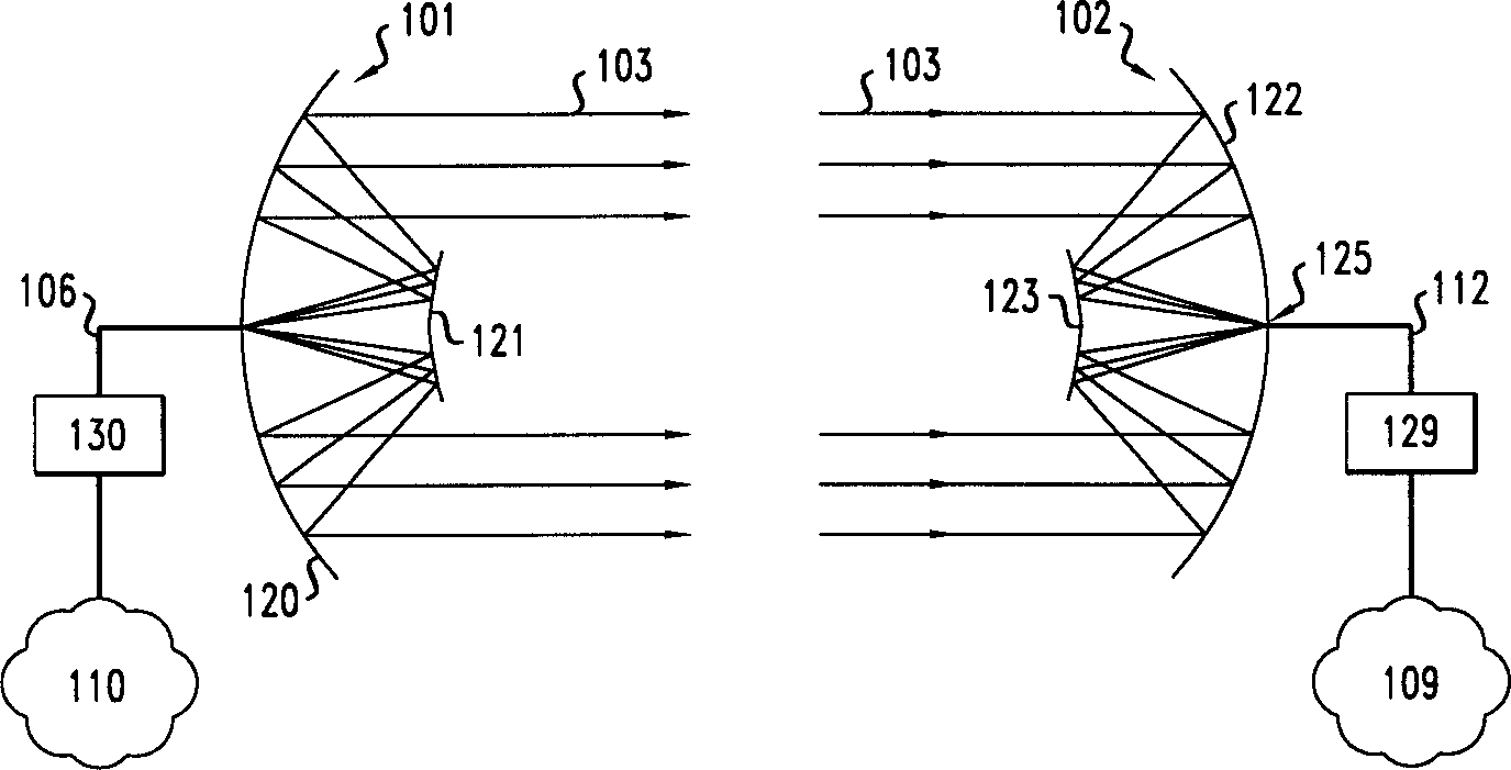
[0014] figure 1 Two prior art telescope optical communication telescopes 101 and 102 in a free space optical communication system are shown during normal calibration operating conditions. A beam of light produced by laser 130 is modulated by data received from network 110 and transmitted through optical fiber 106 . The transmitting telescope 101 receives the modulated optical signal via the optical fiber 106 . Next, the primary mirror 120 and the secondary mirror 121 are optically imaged and emit a beam modulated so that the beam is incident on the focal plane 125 of the receiving telescope 102 . The receiving telescope 102 uses its optical system (including a primary reflector 122 and a secondary reflector 123 ) to focus the incident transmitted modulated light beam 103 onto the receiving optical fiber 112 located on the focal plane 125 of the receiving telescope 102 . The receiving fiber then sends the modulated optical signal to receiver 129 , which converts the optical s...


PUM


Abstract

A free space optical communication system is disclosed whereby the received power at the receive optical fiber is reduced by adjusting the transmitted light beam and the receive optical fiber with respect to each other when a specified power threshold is exceeded so that they intersect not at a point of focus, but at a point of divergence of the transmitted beam. The transmitted beam may be diverged by moving the transmit optical fiber to a point in front of the focal plane of the transmit telesco pe along the longitudinal axis of that telescope until at least a portion of th e beam is incident upon the receive optical fiber. This causes the transmitted beam to diverge and, accordingly, the cross-sectional area to increase at the point where it is incident upon the receive telescope. As a result, the cros s- sectional power per unit area of the transmitted beam at the receive telescope is reduced which correspondingly reduces the power that is incident upon the receive optical fiber.

Description

technical field [0001] The present invention relates generally to data communication systems, and more particularly to free space optical data communication networks. Background technique [0002] To overcome traditional communication systems that use physical wires or cables to connect two or more locations, they are usually limited to relatively low-speed, low-capacity applications. Recently developed systems use optical fiber. Fiber optics, however, still require the use of physical fiber optic cable connections. To solve this problem, systems have been developed that use free space to emit one or more data-modulated beams. Systems using such beams greatly increase data rates and capacity rates, up to 10 gigabits per second, compared to traditional wire-based systems, while avoiding the need for laying fiber optic cables to physically connect various locations in the system in traditional communication systems infrastructure costs incurred. Free-space optical communica...

Claims


Application Information

Patent Timeline
IPC IPC(8): H04B10/07H04B10/11H04B10/112H04B10/118
CPCH04B10/1121
Inventor 赫尔曼·M·普雷斯比约翰·A·泰森
Owner LUCENT TECH INC
Features
  • R&D
  • Intellectual Property
  • Life Sciences
  • Materials
  • Tech Scout
  • Unparalleled Data Quality
  • Higher Quality Content
  • 60% Fewer Hallucinations
Learn More