Optical attenuator

An optical attenuator and dual-fiber collimator technology, applied in the field of optical communication, can solve problems such as high cost and usage restrictions

Inactive Publication Date: 2002-07-03
HUAZHONG UNIV OF SCI & TECH
View PDF0 Cites 8 Cited by
  • Summary
  • Abstract
  • Description
  • Claims
  • Application Information

AI Technical Summary

Problems solved by technology

[0006] Of course, in order to improve the attenuation accuracy, the method of circuit feedback control can be used, but the cost is high and the use is limited

Method used


Image

  • Optical attenuator
  • Optical attenuator
  • Optical attenuator

Examples


Embodiment Construction

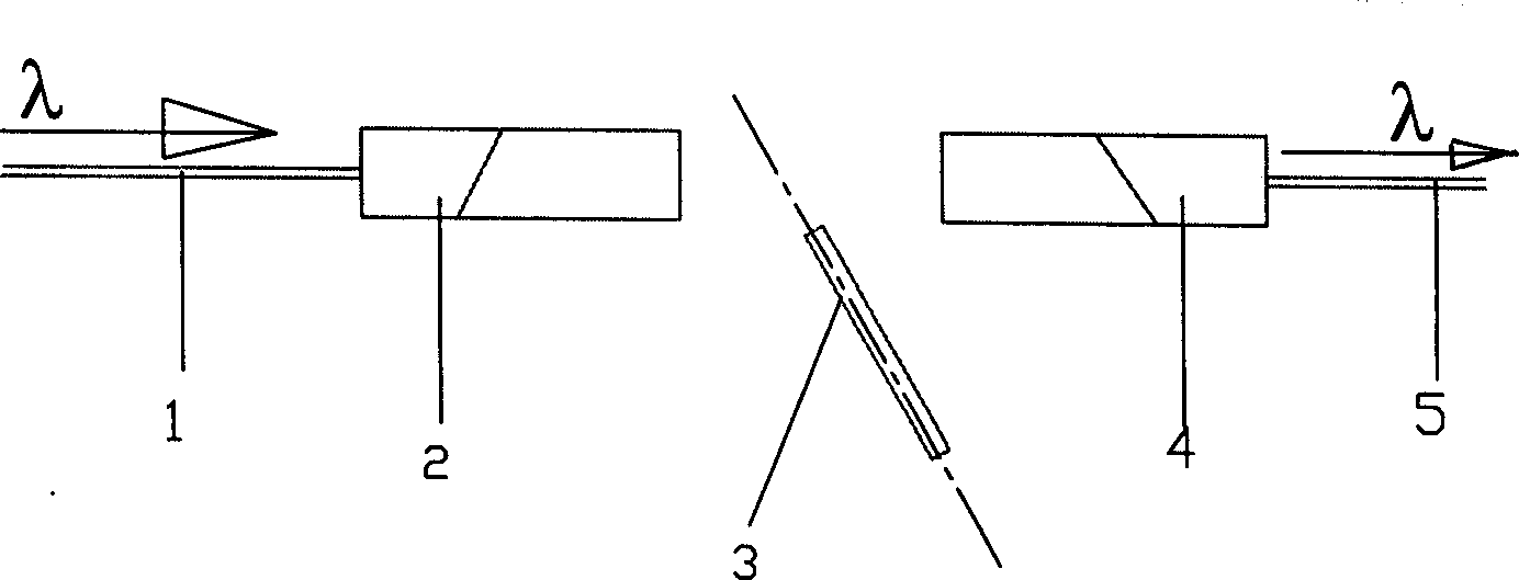
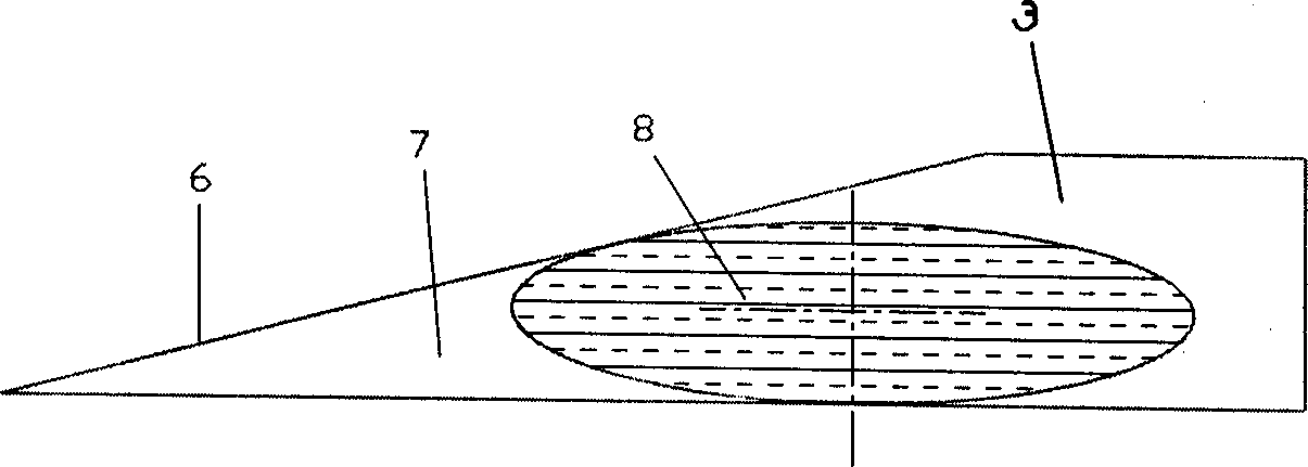
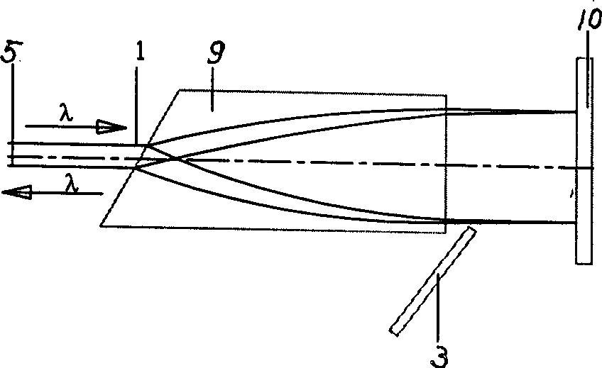
[0018] figure 1 Represent a kind of implementation state of the present invention, wherein, 1,5 are optical fibers, 2 are output fiber collimators, 4 are fiber collimators, 3 are light-blocking sheets, and the moving direction of light-blocking sheet 3 is the same as that of the optical fiber collimator The vertical axis of 2,4 is inclined. Fiber collimators, consisting of quarter-pitch self-focusing (GRIN) lenses and single-mode fiber, are commercially available. The fiber collimator used in this embodiment can expand and collimate the beam into a cylindrical parallel beam with a diameter of 2 mm. The shape of the baffle see figure 2 Light blocker. In this figure, 8 is the oblique section of the ellipse of the cylindrical light beam, and 3 is the light blocking sheet, and the minor axis diameter of the ellipse section 8 should be 2 millimeters. This figure shows the situation that the light beam is completely blocked. When the light is blocked, the edge straight line 6 w...


PUM


Abstract

An optical attenuator for light communication features that two collimators for output and input optical fibres are aligned to each other via an optical coupling path, in which there is a light barrier whose plane has a 10-70 deg of included angle relative to the axis of said optical coupling path. The front shape of said light barrier may be an acute triangle or its one side is straight line and another side is log curve. The said light barrier is driven by micrometer screw gage. Its advantages include high reliability, attenuation precision and echo loss, large ranges of temp, spectrum and big range.

Description

technical field [0001] The invention belongs to the technical field of optical communication, in particular to an optical passive device. Background technique [0002] Optical attenuator is an important fiber optic passive device emerging with the development of optical communication technology, which can be used in optical communication lines, system evaluation, research and adjustment, correction, etc. Traditional optical attenuators can be divided into displacement optical attenuators, direct coating optical attenuators, attenuating plate optical attenuators and liquid crystal optical attenuators. The working principle of displacement optical attenuator is: [0003] When two sections of optical fiber are connected, a relatively high alignment accuracy must be achieved so that the optical signal can be transmitted with a small transmission loss. Conversely, if the alignment accuracy of the fiber is properly adjusted, its attenuation can be controlled. Displacement optic...

Claims


Application Information

Patent Timeline
Patent Type & Authority Applications(China)
IPC IPC(8): G02F1/17
Inventor 许振鄂张立国陆冬生朱大庆
Owner HUAZHONG UNIV OF SCI & TECH
Why Eureka
Try Eureka