Device for clearing surface of roller

A technology of rollers and brush rollers is applied in the field of devices on the surface of rotating rollers, which can solve problems such as hindering the long-term use of the machine.

Inactive Publication Date: 2002-07-24
MASCHINENFABRIK RIETER AG
View PDF0 Cites 9 Cited by
  • Summary
  • Abstract
  • Description
  • Claims
  • Application Information

AI Technical Summary

Problems solved by technology

Due to the very short cleaning cycles of the removal rollers, frequent maintenance by the operator is required, which hinders the long-term use of the machine during periods of no-operator shift

Method used


Image

  • Device for clearing surface of roller
  • Device for clearing surface of roller

Examples


Embodiment Construction

[0026] Description of preferred embodiments

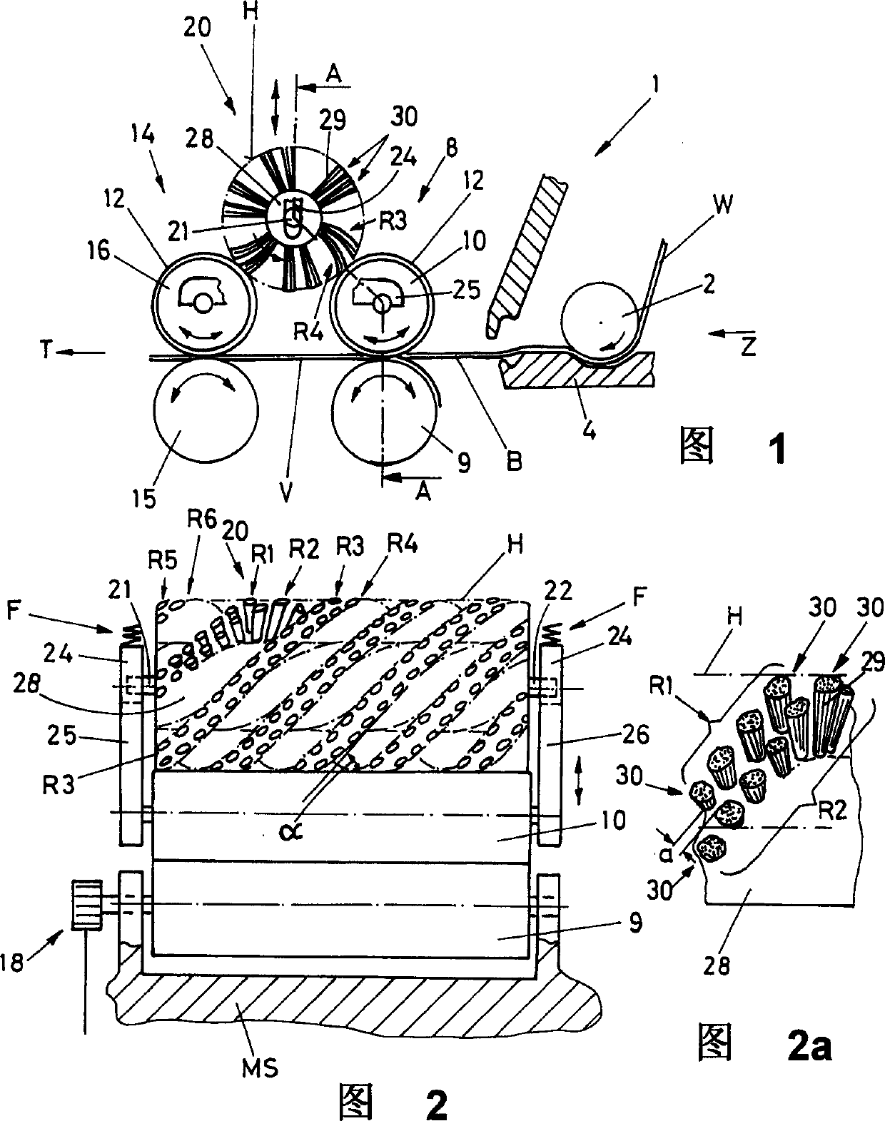
[0027] FIG. 1 shows a partial view of a nipper assembly 1 with a feed roller 2 attached. A degreased cotton W unwound from the final lap (not shown) passes through the feed roller 2 cooperating with the feed plate (not shown in detail) of the lower nipper 4 by the nipper movement Z along the separation roller pair 8 direction conveying. The detaching roller pair 8 here comprises a driven moving roller 9 and a pressure roller 10 which is pressed in the direction of the roller 9 by means of a loading device schematically indicated by a spring F ( FIG. 2 ). The pressure roller 10 is covered with a rubber layer 12 for this purpose. Behind the pair of rollers 8 there is a further pair of rollers 14 which comprises a fixedly mounted driven roller 15 and a pressure roller 16 . The pressing roller 16 is pressed by the same loading device in the direction of the roller 15 and likewise has a rubber layer 12 . Rollers 9 and 15 are driven ...


PUM


Abstract

The invention reolates to a rotary roller device for cleaning textile machine comprising a freely rotated cleaning piece (20) mounted on roller which is movably supported by guide piceces (21,22,24). In order to improve the cleaning effect and prolong the maintenance period, it is suggested that the cleaning piece should be constructed by brush roller (20).

Description

technical field [0001] The invention relates to a device for clearing the surface of a rotating roller of a textile machine, comprising a free-rotating clearing element arranged on the surface of the roller, which is movable and supported in the vertical direction by a guide element. Background technique [0002] For conveying or processing textile materials, pressurized rollers are used in textile machines, which rest against drive rollers via corresponding loading devices. During the rotational operation by the drive rollers, the pressure rollers, generally covered with a rubber layer, are displaced by friction. Such roller pairs are used on drafting rollers, spinning frames and combing machines. [0003] In combing machines, such roller pairs are used in particular for the separation process of combed fiber tufts. Its fiber web or fiber, such as cotton fiber, is clamped and conveyed between the pressing roller and the roller through the jaw line. [0004] In the proces...

Claims


Application Information

Patent Timeline
Patent Type & Authority Applications(China)
IPC IPC(8): D01G15/80
CPCD01G15/80
Inventor F·卡瓦蒂尼W·施莱普菲
Owner MASCHINENFABRIK RIETER AG
Why Eureka
Try Eureka