
Electronic structure and forming method thereof

An electronic structure, atomic technology, applied in chemical instruments and methods, circuits, electrical components, etc., can solve problems such as pure copper not well attached, device failure, etc.

Inactive Publication Date: 2010-05-26
GLOBALFOUNDRIES INC
View PDF2 Cites 0 Cited by
  • Summary
  • Abstract
  • Description
  • Claims
  • Application Information

AI Technical Summary

Problems solved by technology

Any diffusion of copper atoms into the silicon substrate will cause device failure
Also, pure copper does not adhere well to oxygen-containing insulating materials such as silicon dioxide and polyimide

Method used

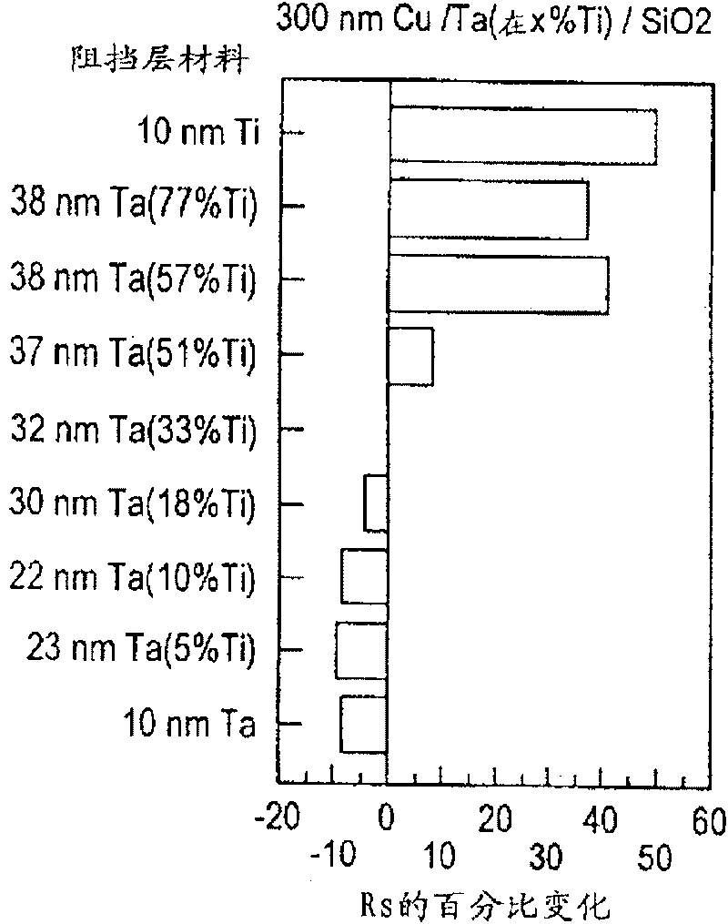
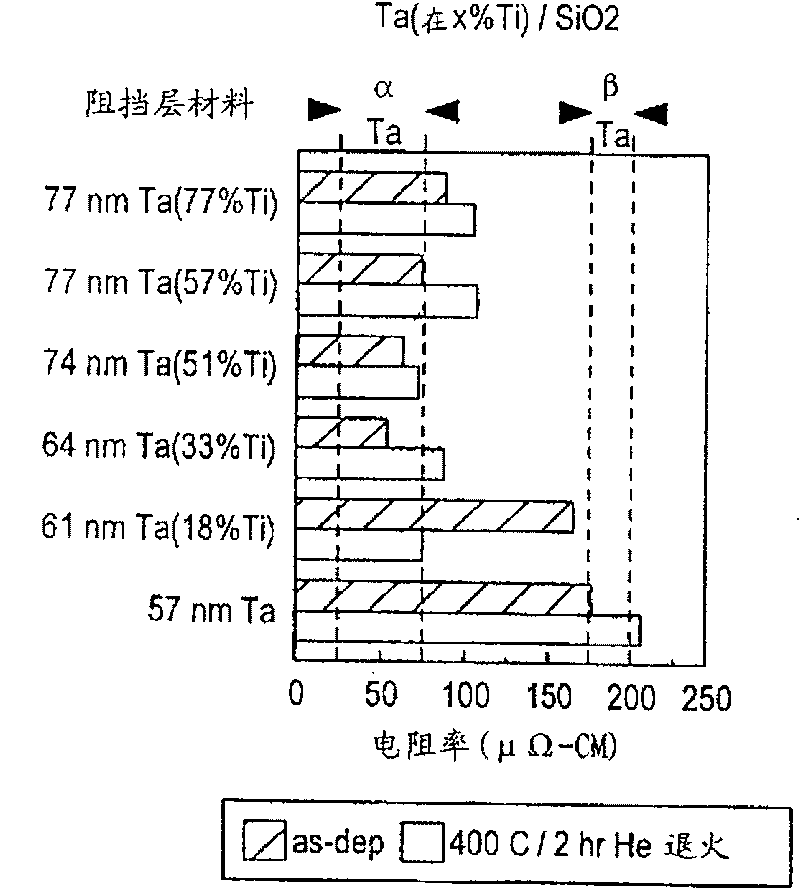
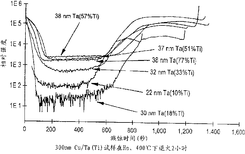

Image

  • Electronic structure and forming method thereof
  • Electronic structure and forming method thereof
  • Electronic structure and forming method thereof

Examples


Embodiment Construction

[0030] The present invention discloses an electrical conductor formed in an electronic structure and a lining for such an electrical conductor in the electronic structure.

[0031] Electrical conductors formed in electronic structures provided by the present invention may include a body of the electrical conductor and a liner adjoining the body of the electrical conductor. The conductor body is formed of an alloy containing elements selected from Ti, Zr, In, Sn and Hf between about 0.001% (atom) and about 2% (atom), and the lining includes Ta, W , Ti, Nb and V alloy formation.

[0032]The present invention further discloses a lining for semiconductor inner connectors, which is selected from Ti, Hf, In, Sn, Zr and their alloys, TiCu 3 、 Ta 1-X Ti X 、 Ta 1-X f X 、 Ta 1-X In X 、 Ta 1-X sn X 、 Ta 1-X Zr X formed by the material in.

[0033] The invention also discloses a method for forming an electronic structure, which includes the following steps: firstly forming an ...


PUM


Abstract

An electrical conductor for use in an electronic structure is disclosed which includes a conductor body that is formed of an alloy including between about 0.001 atomic % and about 2 atomic % of an element selected from the group consisting of Ti, Zr, In, Sn and Hf; and a liner abutting the conductor body which is formed of an alloy that includes Ta, W, Ti, Nb and V. The invention further disclosesa liner for use in a semiconductor interconnect that is formed of a material selected from the group consisting of Ti, Hf, In, Sn, Zr and alloys thereof, TiCu3, Ta1-XTix, Ta1-XHfx, Ta1-XInxy, Ta1-XSnx, Ta1-XZrx.

Description

technical field [0001] The present invention generally relates to a method of forming an electrical conductor in an electronic structure, and more particularly, the present invention relates to a method of forming an electrical conductor containing up to 2 atomic percent impurity elements and is surrounded by Ti-containing lining around. Background technique [0002] Over the past decade, techniques for fabricating metal conductors to provide vias, lines, and other recesses in semiconductor chip structures, flat panel displays, and application package assemblies have been developed. For example, in the development of interconnect technology for very large scale integration (VLSI) structures, aluminum is used as the main metal source for contacts and interconnects in semiconductor regions on a single substrate or in semiconductor devices. Aluminum has been the material of choice due to its low price, good ohmic contact, and high electrical conductivity. However, pure alumin...

Claims


Application Information

Patent Timeline
Patent Type & Authority Patents(China)
IPC IPC(8): H01L23/532H01L21/768H01L21/28H01L21/3205H01B1/02B32B15/01C22C27/02
CPCY10S428/929Y10S428/936H01L21/76843Y10S428/938Y10S428/935B32B15/01H01L23/53223H01L23/53238H01L21/76846C22C27/02H01L2924/0002Y10T428/12639Y10T428/12743Y10T428/12806Y10T428/12812Y10T428/12819Y10T428/12826Y10T428/12833Y10T428/1284Y10T428/12903H01L2924/00H01L21/28
Inventor 小西里尔·卡布拉尔罗伊·A·卡拉瑟斯詹姆斯·M·E·哈珀胡朝坤李金阳伊斯梅尔·C·诺延罗伯特·罗森伯格托马斯·M·肖
Owner GLOBALFOUNDRIES INC
Learn More