Radio communication apparatus and method

A wireless communication device and wireless communication technology, applied in multiplexing communication, radio transmission system, communication between multiple stations, etc., can solve the problem of inability to reduce multipath distortion, inability to obtain frequency diversity effect, and inability to separate paths And other issues

Inactive Publication Date: 2002-08-14
PANASONIC CORP
View PDF2 Cites 12 Cited by
  • Summary
  • Abstract
  • Description
  • Claims
  • Application Information

AI Technical Summary

Problems solved by technology

[0013] However, in the time domain extension method, if one focuses on a certain digital symbol, then since the expanded chips become time-sequentially arranged in the same frequency ( figure 2 and image 3 ), so the path diversity effect of multipath separation can be obtained, but the frequency diversity effect cannot be obtained
[0014] Therefore, when the transmission power control corresponding to the radio channel condition is incomplete, the transmission characteristic is severely deteriorated.
In addition, even when the transmission power control is fully performed, the transmission power is increased based on this control, but there are problems such as increased battery consumption of the mobile station device, increased amplifier size, and increased interference with other cells.
[0015] In the frequency domain extension method, if one focuses on a certain digital symbol, since a plurality of extended chips are arranged in different subcarriers at the same time ( Figure 4 and Figure 5 ), so the frequency diversity effect can be obtained, but the path separation cannot be performed and the path diversity effect cannot be obtained
[0016] Therefore, multipath distortion cannot be reduced since RAKE combining is not possible
In the case of code-division-multiplexing signals of multiple users in each subcarrier, even if orthogonal codes are used in spreading processing, the orthogonality cannot be maintained due to the influence of multipath distortion, so the code-division multiplexing number is limited
In addition, the influence of a shift in signal cutting timing at the time of Fourier transform increases

Method used


Image

  • Radio communication apparatus and method
  • Radio communication apparatus and method
  • Radio communication apparatus and method

Examples


Embodiment 1

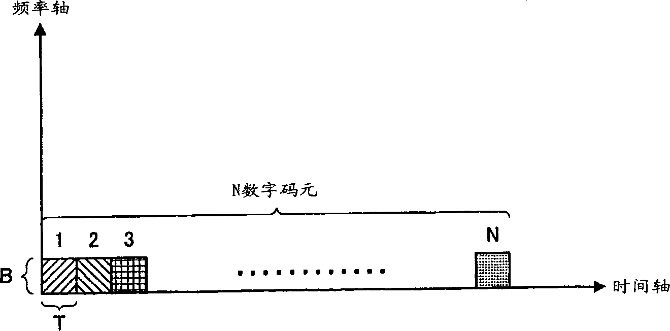
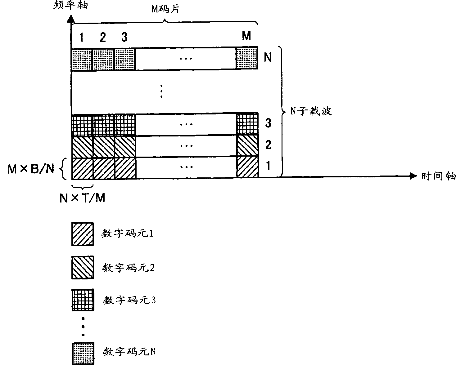
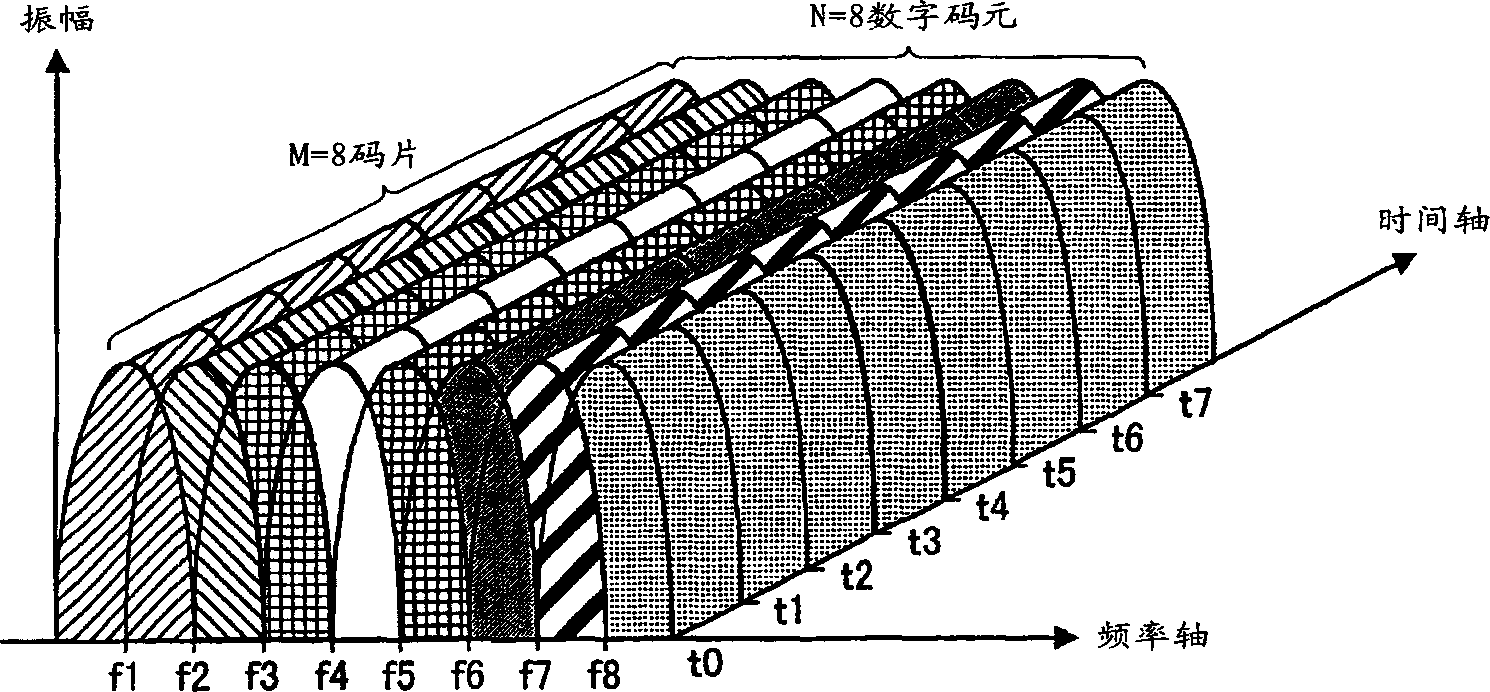
[0045] In this embodiment, the data is expanded on the time axis, and the expanded chips are moved in segments along the rising or falling direction of the carrier on the frequency axis to perform configuration transformation, and a certain data is allocated on the frequency axis and the time axis. Both come up for a two-dimensional configuration.

[0046] Figure 6 A block diagram showing the configuration of the transmitting end in the wireless communication device according to Embodiment 1 of the present invention. Figure 6 The shown wireless communication device at the transmitting end includes a serial / parallel conversion unit (S / P unit) 101, time zone extenders 102-1 to 102-N, a configuration switching unit 103, an inverse Fourier transform unit (IFFT unit) 104, A wireless transmission unit 105 and an antenna 106 .

[0047] Figure 7 A block diagram showing the configuration of the receiving end in the wireless communication device according to Embodiment 1 of the pr...

Embodiment 2

[0066] In this embodiment, data is spread in both the frequency domain and the time domain, that is, by spreading data in both the direction of the frequency axis and the direction of the time axis, a certain data is distributed on both the time axis and the frequency axis. Two-dimensional configuration.

[0067] Figure 10 A block diagram showing the configuration of the transmitting end in the wireless communication device according to Embodiment 2 of the present invention. Figure 10 The wireless communication device at the sending end shown includes a frequency domain extender 301, an S / P unit 101, and time domain extenders 102-1 to 102-M 1 , IFFT unit 104, wireless transmission unit 105, and antenna 106. exist Figure 10 In, for example 1 ( Figure 6 ) with the same structure as Figure 6 The same reference numerals are used, and detailed descriptions are omitted.

[0068] Figure 11 A block diagram showing the configuration of the receiving end in the wireless commu...

Embodiment 3

[0087] In this embodiment, after the data is spread in both the frequency domain and the time domain, the configuration conversion is performed by moving the spread chips on the frequency axis in sections along the rising or falling direction of the carrier frequency.

[0088] Figure 17 A block diagram showing the structure of the transmitting end in the wireless communication device according to Embodiment 3 of the present invention. Figure 17 The wireless communication device at the sending end shown in the wireless communication device of Embodiment 2 ( Figure 10 ) time zone expander 102-1 ~ 102-M1 Between the IFFT unit 104 and the configuration switching unit 103 described in the first embodiment. exist Figure 17 In, for example 1 ( Figure 6 ) or Example 2 ( Figure 10 ) are attached with the same symbols as them, and detailed explanations are omitted.

[0089] Figure 18 A block diagram showing the configuration of the receiving end in the wireless communicatio...


PUM


Abstract

Time range spreaders (102-1 to 102-N) are used to spread, along the time axis, data that have been parallel converted by an S / P section (101). A rearranging unit (103) is used to shift the spread chip stepwise in the upward or downward direction of the carrier frequency to rearrange them along the frequency axis. In this way, a piece of data is divided along the frequency and time axes and arranged in a two-dimensional manner.

Description

technical field [0001] The present invention relates to a wireless communication device and a wireless communication method used in a digital communication system, in particular to multi-carrier modulation methods such as OFDM (Orthogonal Frequency Division Multipexing: Orthogonal Frequency Division Multiplexing) modulation methods and CDMA (Code Division Multiple Access: A wireless communication device and a wireless communication method that perform wireless communication by combining code division multiple access) methods. Background technique [0002] In recent years, in wireless communication, especially mobile communication, various kinds of information such as images and data are targeted for transmission in addition to voice. It can be expected that the demand for transmission of various contents will increase in the future, so the necessity for highly reliable and high-speed transmission will further increase. However, in the case of high-s...

Claims


Application Information

Patent Timeline
Patent Type & Authority Applications(China)
IPC IPC(8): H04B1/69H04B1/707H04B7/26H04J13/00H04L1/00H04L5/02H04L27/26
CPCH04B1/692H04L27/2608H04B7/2628H04L5/026H04L1/0071H04B1/707H04L5/0044H04L27/26
Inventor 上杉充须增淳
Owner PANASONIC CORP
Why Eureka
Try Eureka