Cutting equipment for brush

A technology for cutting equipment and shrubs, which is applied in the direction of cutting equipment, cutters, cutting tools, etc., and can solve problems such as time-consuming and labor-intensive

Inactive Publication Date: 2002-09-04
HONDA MOTOR CO LTD
View PDF1 Cites 17 Cited by
  • Summary
  • Abstract
  • Description
  • Claims
  • Application Information

AI Technical Summary

Problems solved by technology

Also, an extra operation is required to check and adjust the tension of the connecting wire attached to the other end of the rod, which will be extra time-consuming and labor-intensive

Method used


Image

  • Cutting equipment for brush
  • Cutting equipment for brush
  • Cutting equipment for brush

Examples


Embodiment Construction

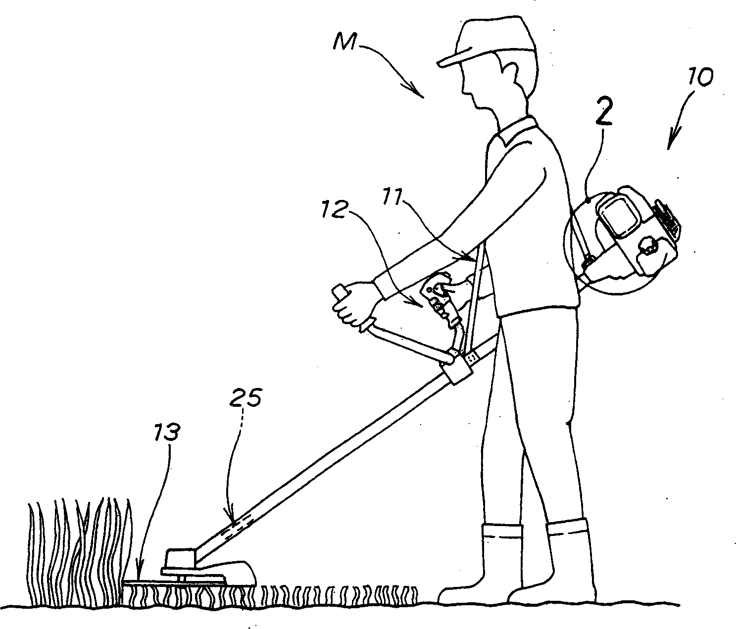
[0023] figure 1 It is a view showing the manner in which an operator cuts a bush using the bush cutting device according to the first embodiment of the present invention. That is, the operator shown here carries the bush cutting device 10 with a strap 11 suspended from one shoulder of the operator, and grasps the manipulating portion 12 of the cutting device 10 with one of his or her hands. The bush cutting device 10 includes a rotary cutting blade 13 and various other components which will be described in detail below.

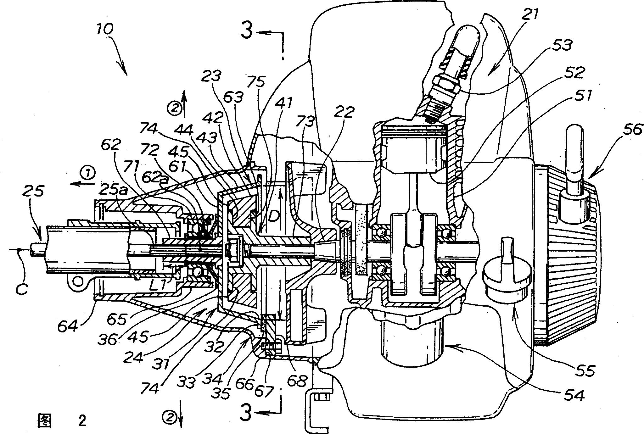
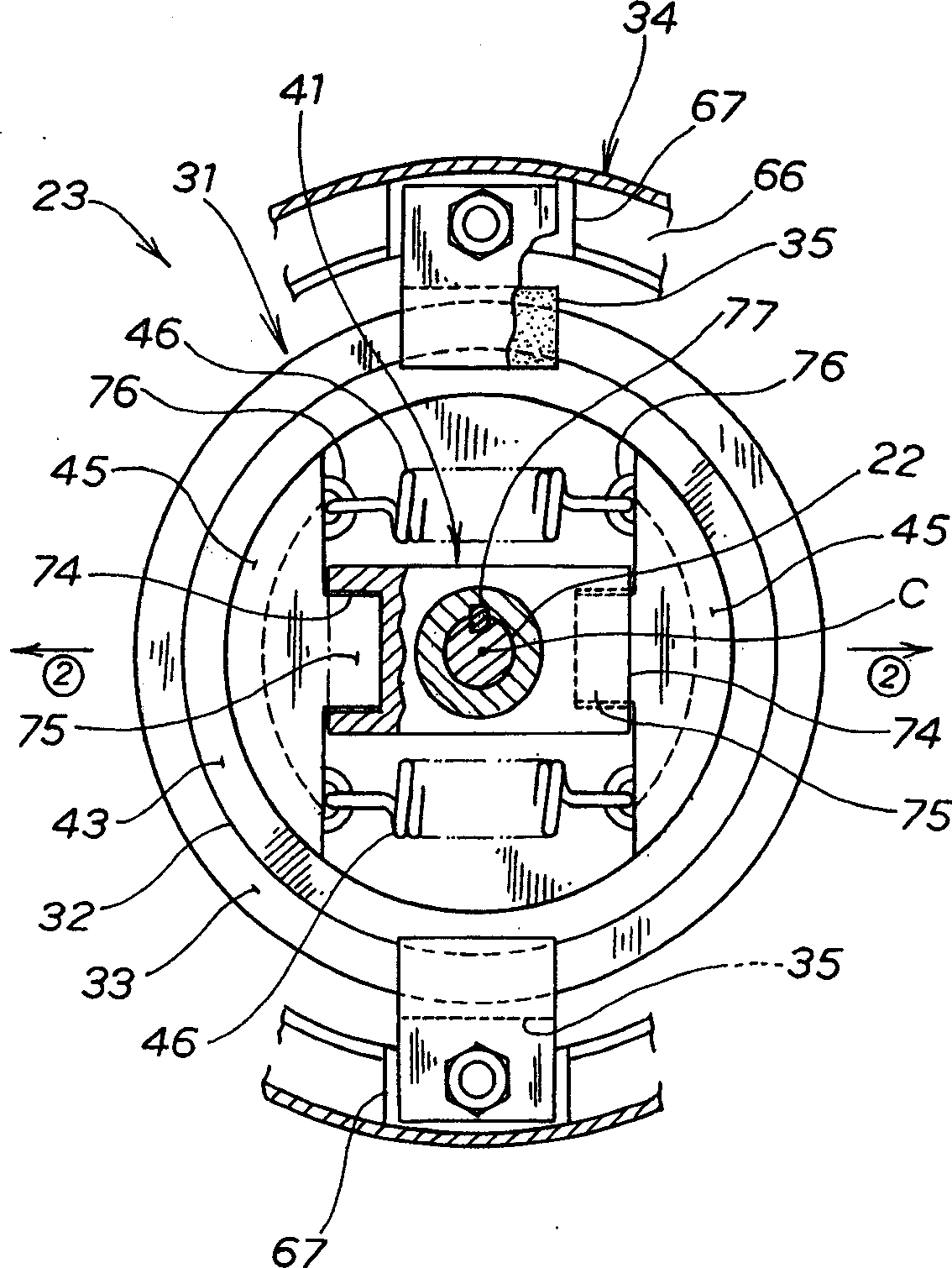
[0024] Figure 2 is figure 1 Partial sectional front view of the body section of the cutting device 10 circled by 2 in . As shown, the brush cutting apparatus 10 includes a prime mover or drive source 21 , a clutch mechanism 23 and a braking mechanism 24 connected to a crankshaft 22 of the drive source 21 , and a cutting blade drive shaft 25 connected to the clutch mechanism 23 .

[0025]The clutch mechanism 23 includes a rotary element 41 mounted on the cr...


PUM


Abstract

When the rotation speed of the driving source (21) has been lower than a predetermined value, the clutch moving element (45; 85) is disengaged from the clutch drum (31; 81) under the action of the clutch elastic element (46), thus making the clutch drum (31; 81) elastically slides back to a predetermined braking position under the action of the braking elastic element (36), where the brake shoe (33; 83) presses against the brake pad (35) to apply Braking action. When the rotational speed of the source device (21) has increased beyond a predetermined value, the clutch moving element (45; 85) slides radially outwards under centrifugal force in such a way that the clutch moving element (45; 85) Overcoming the bias of the brake elastic element (36), applying pressure to the clutch drum (31; 81) and making the clutch drum (31; 81) axially slide to the non-braking position, so that the brake shoe (33; 83 ) is disengaged from the brake pad (35) to release the braking effect.

Description

technical field [0001] The present invention relates generally to bush cutting equipment and, more particularly, to an improved braking mechanism for stopping rotation of the cutting blade of the bush cutting equipment. Background technique [0002] Brake mechanisms for bush cutting equipment are known, for example, from Japanese Utility Model Laid-Open Nos. 51-53248 and 51-99039. The first-mentioned 51-53248 application discloses a bush cutting apparatus including a brake shoe and a cam disc for moving the brake shoe into and out of engagement with a driven shaft. When the operator releases the brake lever, the spring pivots the cam plate to press the brake shoe against the driven shaft, thereby automatically generating a braking force to stop the rotation of the rotary tool. [0003] The second mentioned 51-99039 application discloses a bush cutting device including a pad disposed along the outer periphery of the clutch drum. When the operator releases the lever, the bra...

Claims


Application Information

Patent Timeline
Patent Type & Authority Applications(China)
IPC IPC(8): A01D34/76A01D34/68A01D34/90F16D43/18F16D59/02F16D65/14
CPCA01D34/6812A01D34/90A01D2101/00F16D59/02F16D2121/14F16D2121/16F16D2123/00F16D2129/043A01D34/68
Inventor 藁科诚小林隆夫
Owner HONDA MOTOR CO LTD
Why Eureka
Try Eureka