Lubricating structure for OHC engine

一种润滑结构、发动机的技术,应用在发动机元件、阀附件的润滑、机器/发动机等方向,能够解决飞溅、难滑油、滑油不充分等问题

Inactive Publication Date: 2002-09-25
HONDA MOTOR CO LTD
View PDF2 Cites 6 Cited by
  • Summary
  • Abstract
  • Description
  • Claims
  • Application Information

AI Technical Summary

Problems solved by technology

[0005] Even according to the lubricating structure of Japanese Patent Application Laid-Open No. 9-151720, it is difficult to evenly splash lubricating oil into the valve operating chamber, and it may be so that, among the parts forming the valve operating system, the oil is placed on the tight side of the timing belt There may not be enough oil supplied to the components on the

Method used


Image

  • Lubricating structure for OHC engine
  • Lubricating structure for OHC engine
  • Lubricating structure for OHC engine

Examples


Embodiment Construction

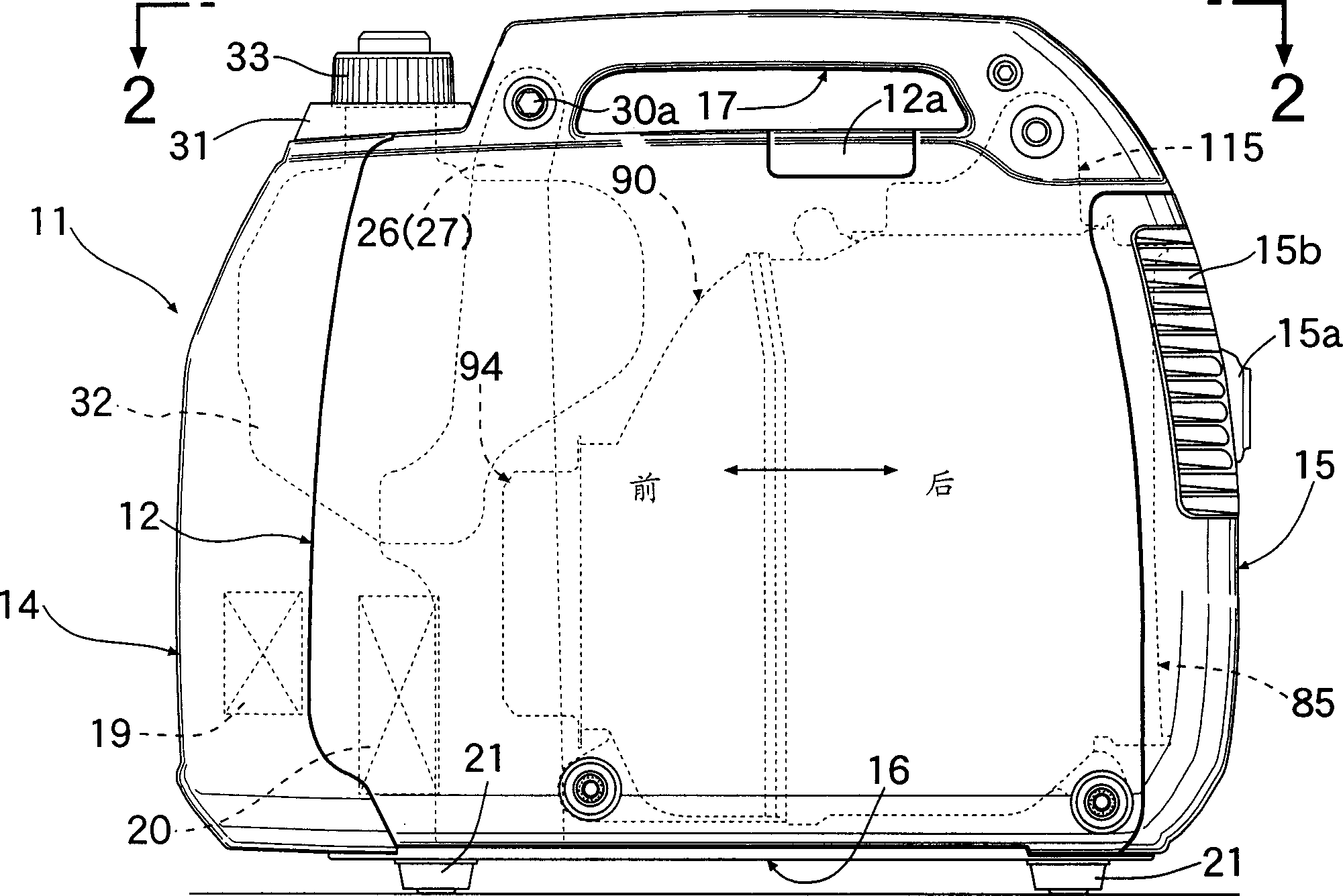
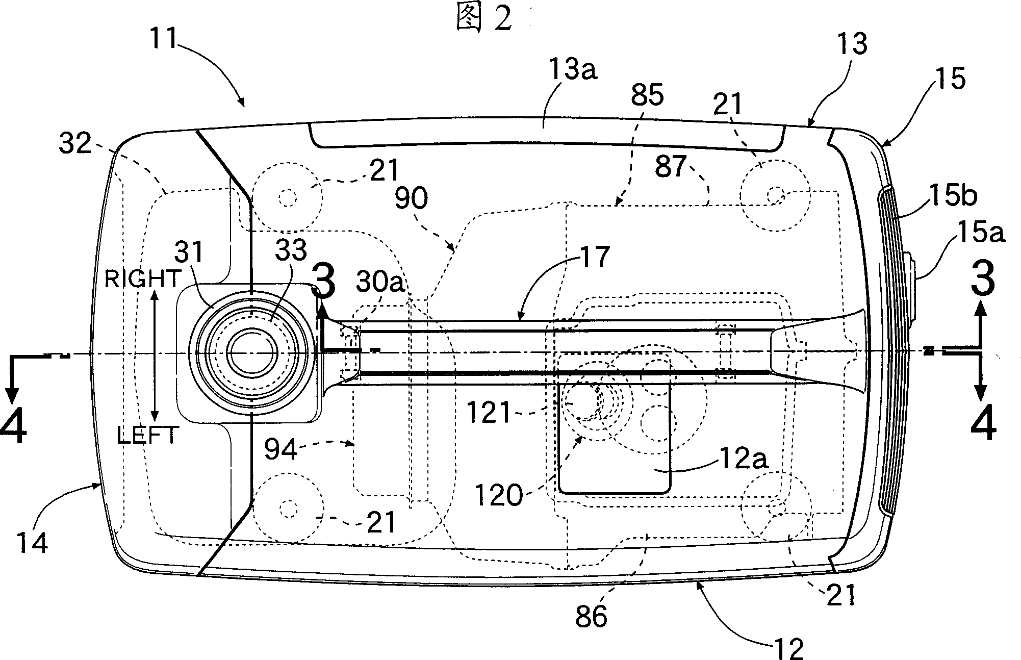
[0026] The following will refer to Figures 1 to 14 An embodiment of the present invention will be described. refer to figure 1 To 4, the synthetic resin casing 11 forms the housing of the portable engine generator set, which is a portable engine-driven machine. The casing 11 is formed of a left side cover 12 , a right side cover 13 , a front cover 14 , a rear cover 15 , and a bottom cover 16 connected to each other. There is a carrying handle 17 on the top of the left and right side covers 12 and 13, so as to carry the engine generator set. Radial reinforcement ribs 17a are formed in the carrying handle 17 as shown in FIG. 4 .

[0027] The left side cover 12 has a cap 12a which can be opened and closed for spark plug replacement. The right side cover 13 has a cap 13a which can be opened and closed for maintenance. The front cover 14 has a control panel 18 . On the inner surface of the control panel 18 is a control unit for controlling the operation of the engine E and t...


PUM


Abstract

An OHC engine includes a valve operating system installed in a valve operating chamber formed between a cylinder head and an end cover connected to the cylinder head. The valve operating system includes a valve operating cam, which is matched and connected with an intake valve and an exhaust valve. The OHC engine also includes a synchronous transmission arranged between the valve operating system and the crankshaft, the synchronous transmission includes a driven wheel and a transmission belt, the driven wheel rotates with the valve operating cam, and the transmission belt runs around The driven wheel, in this way, the lubricating oil in the crankcase can move with the transmission belt and supply the valve operating chamber. The end cap has an arcuate curved cover portion for covering the upper portion of the driven wheel. The curved cover part integrally includes a plurality of oil splashing ribs on the driven wheel, the oil splashing ribs are arranged at intervals along the rotation direction of the driven wheel, and protrude toward the side closer to the conveying belt, so that the lubricating oil can be evenly distributed. Supply all parts of the valve operating system.

Description

technical field [0001] The present invention relates to an OHC engine in which a valve operating system is housed in a valve operating chamber formed between a cylinder head and an end cover connected to the cylinder head. The valve operating system includes: a valve operating cam, which is rotatably supported by the cylinder head, and is connected with an intake valve and an exhaust valve; and a synchronous transmission device, which is arranged on the valve between the operating system and the crankshaft. The synchronous transmission device includes: a driven wheel, which rotates together with the valve operating cam; and a transmission belt, which surrounds the driven wheel, so that the lubricating oil in the crankcase is carried by the transmission belt and supplied to the valve operation chamber . In particular, the present invention relates to improvements in lubrication arrangements for valve operating systems. Background technique [0002] For example, Japanese Pa...

Claims


Application Information

Patent Timeline
Patent Type & Authority Applications(China)
IPC IPC(8): F01M9/06F01M9/10F02B63/04F02B75/16F02F7/00
CPCF01M9/10F02B63/04F02B75/16F02B2063/046F02F7/006F01L1/182F01L1/20F01L2001/0535
Inventor 佐藤义一片山伸二
Owner HONDA MOTOR CO LTD
Why Eureka
Try Eureka