Dialysis system and its operation method
A dialyzer and dialysate technology, applied in the field of dialysis system, can solve problems such as troublesome operation of dialysis system, achieve the safety of extracorporeal circulation and blood purification, and realize the effect of saving operation, time and labor
- Summary
- Abstract
- Description
- Claims
- Application Information
AI Technical Summary
Problems solved by technology
Method used
Image

Examples
Embodiment Construction
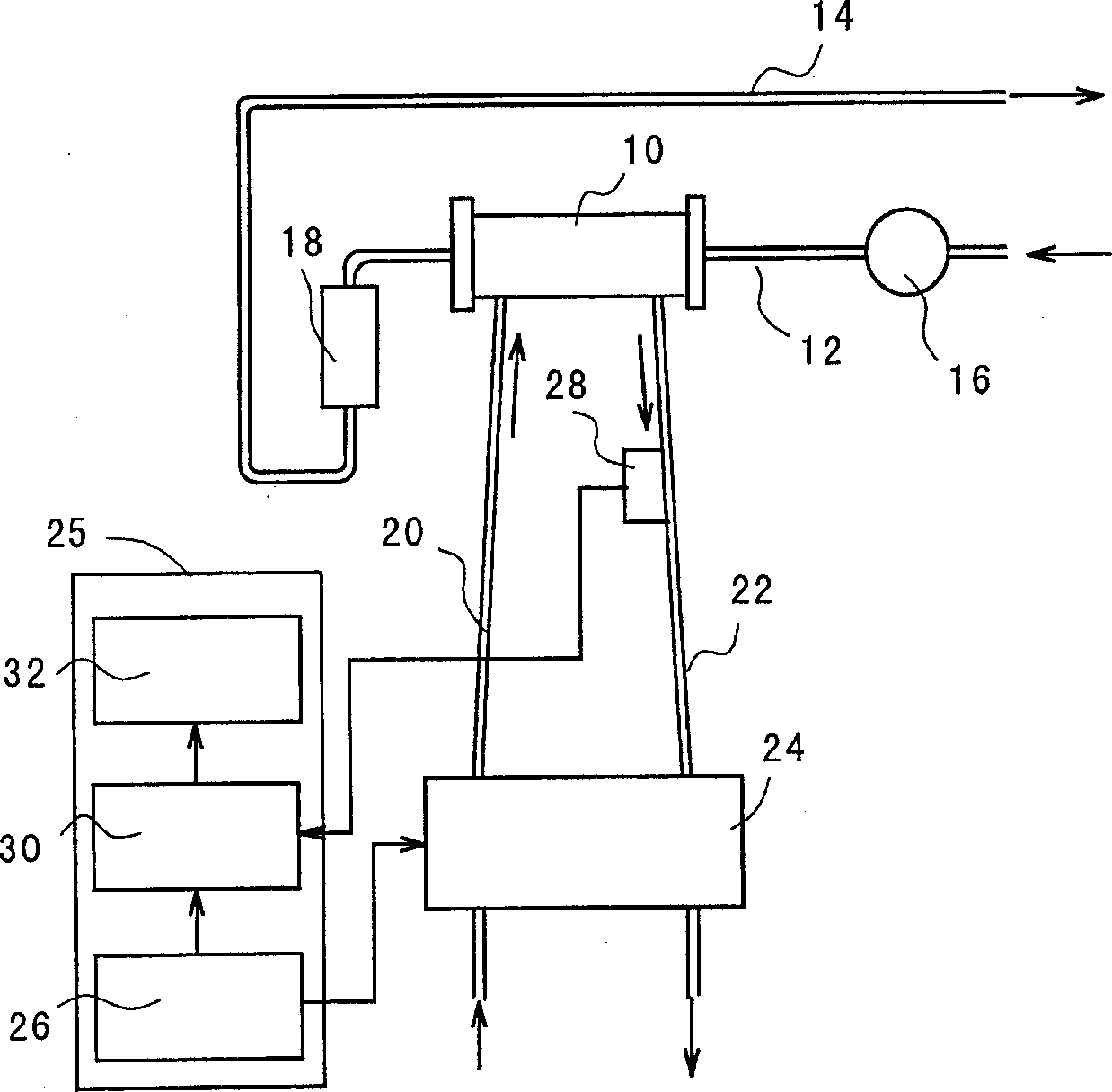
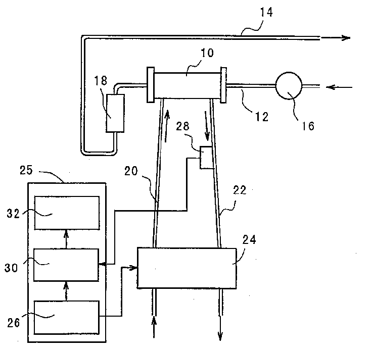
[0029] refer to figure 1 , which shows a schematic diagram illustrating one embodiment of the dialysis system of the present invention. exist figure 1 In , reference numeral 10 denotes a dialyzer or purifier for blood purification of a known structure, which includes, for example, a cylindrical housing and a semi-permeable hollow filter membrane located in the housing.
[0030] One end of the dialyzer 10 is connected to a blood inflow tube 12 for drawing blood from a patient, and the other end is connected to a blood outflow tube 14 for returning purified blood to the patient. In other words, the blood flow tube includes a blood inflow tube 12 for drawing blood from a patient, a blood flow portion in the dialyzer 10, and a blood outflow tube 14 for returning purified blood to the patient. The blood inflow line 12 has a blood pump 16 for flowing blood through the blood inflow line 12 , the dialyzer 10 and the blood outflow line 14 . On the other hand, the blood outflow tube ...
PUM
 Abstract
Description
Claims
Application Information
 - Generate Ideas
- Intellectual Property
- Life Sciences
- Materials
- Tech Scout
- Unparalleled Data Quality
- Higher Quality Content
- 60% Fewer Hallucinations
Browse by: Latest US Patents, China's latest patents, Technical Efficacy Thesaurus, Application Domain, Technology Topic, Popular Technical Reports.
© 2025 PatSnap. All rights reserved.Legal|Privacy policy|Modern Slavery Act Transparency Statement|Sitemap|About US| Contact US: help@patsnap.com