PLL loop filter with switched-capacitor resistor

A loop filter, switching circuit technology, applied in the direction of electrical components, automatic control of power, etc., can solve problems such as thermal noise affecting the output signal of the phase-locked loop

Inactive Publication Date: 2002-10-30
TELEFON AB LM ERICSSON (PUBL)
View PDF0 Cites 36 Cited by
  • Summary
  • Abstract
  • Description
  • Claims
  • Application Information

AI Technical Summary

Problems solved by technology

This resistor generates thermal noise large enough to affect the phase noise spectrum of the PLL output signal
In the vicinity of the loop bandwidth, the loop filter resistor noise may dominate the overall phase noise

Method used


Image

  • PLL loop filter with switched-capacitor resistor
  • PLL loop filter with switched-capacitor resistor
  • PLL loop filter with switched-capacitor resistor

Examples


Embodiment Construction

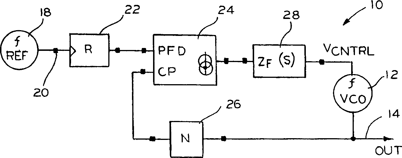
[0019] first reference figure 1 , a typical implementation of a phase locked loop circuit 10 may be used to generate a local oscillator signal in a radio receiver or transmitter, such as a cellular telephone. The circuit 10 includes a voltage controlled oscillator (VCO) 12 that generates an oscillating output signal on line 14 in response to a voltage controlled input on line 16 . Reference source 18 provides a reference frequency signal on line 20 . The reference frequency signal on line 20 is coupled via a first divider 22 to an input of a phase detector 24 . The oscillating output signal on line 14 is connected to a second input of a phase detector 24 through a second divider 26 . In particular, the reference frequency signal is divided by the reference division ratio R. Similarly, the oscillating output signal is divided by the main scale ratio N.

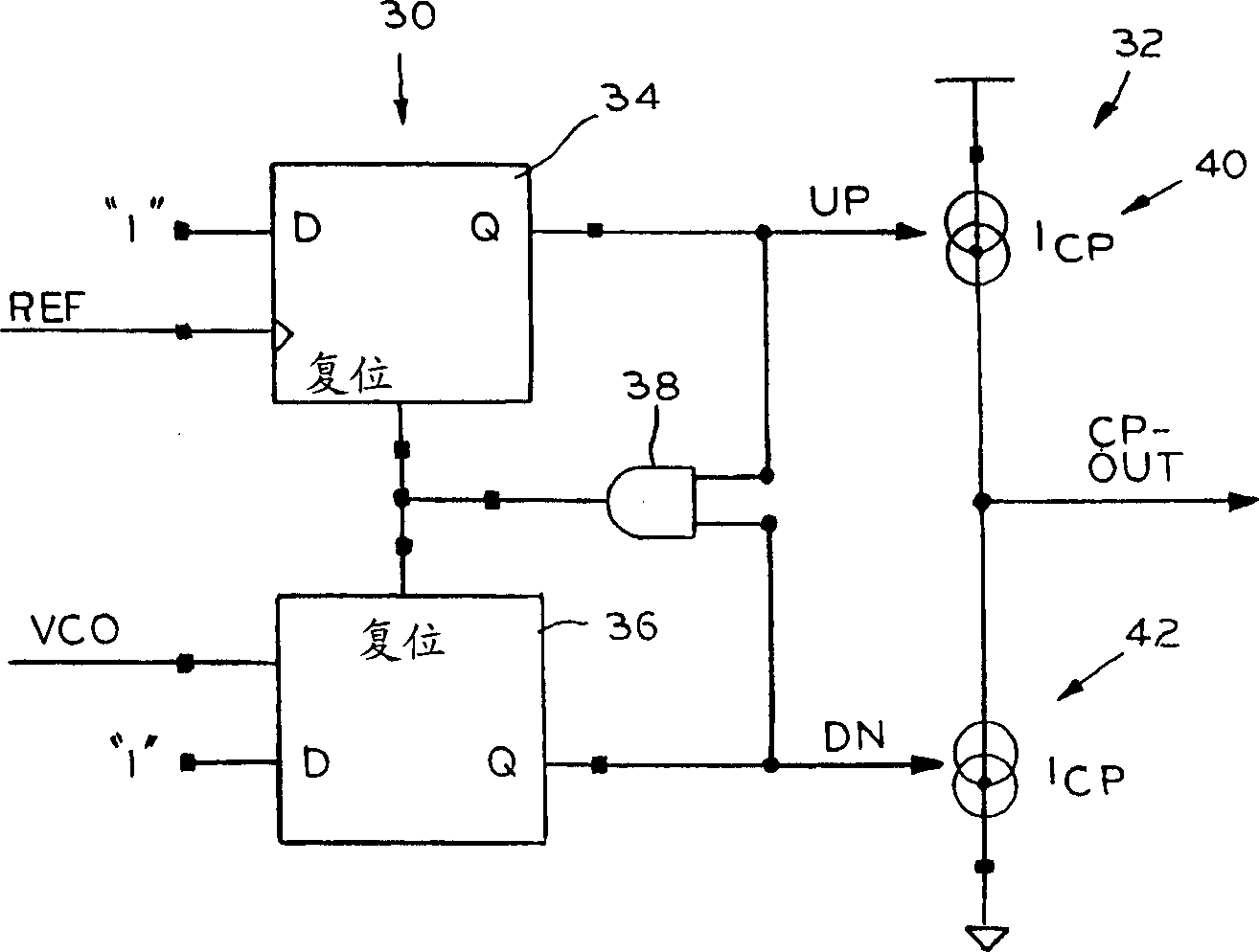
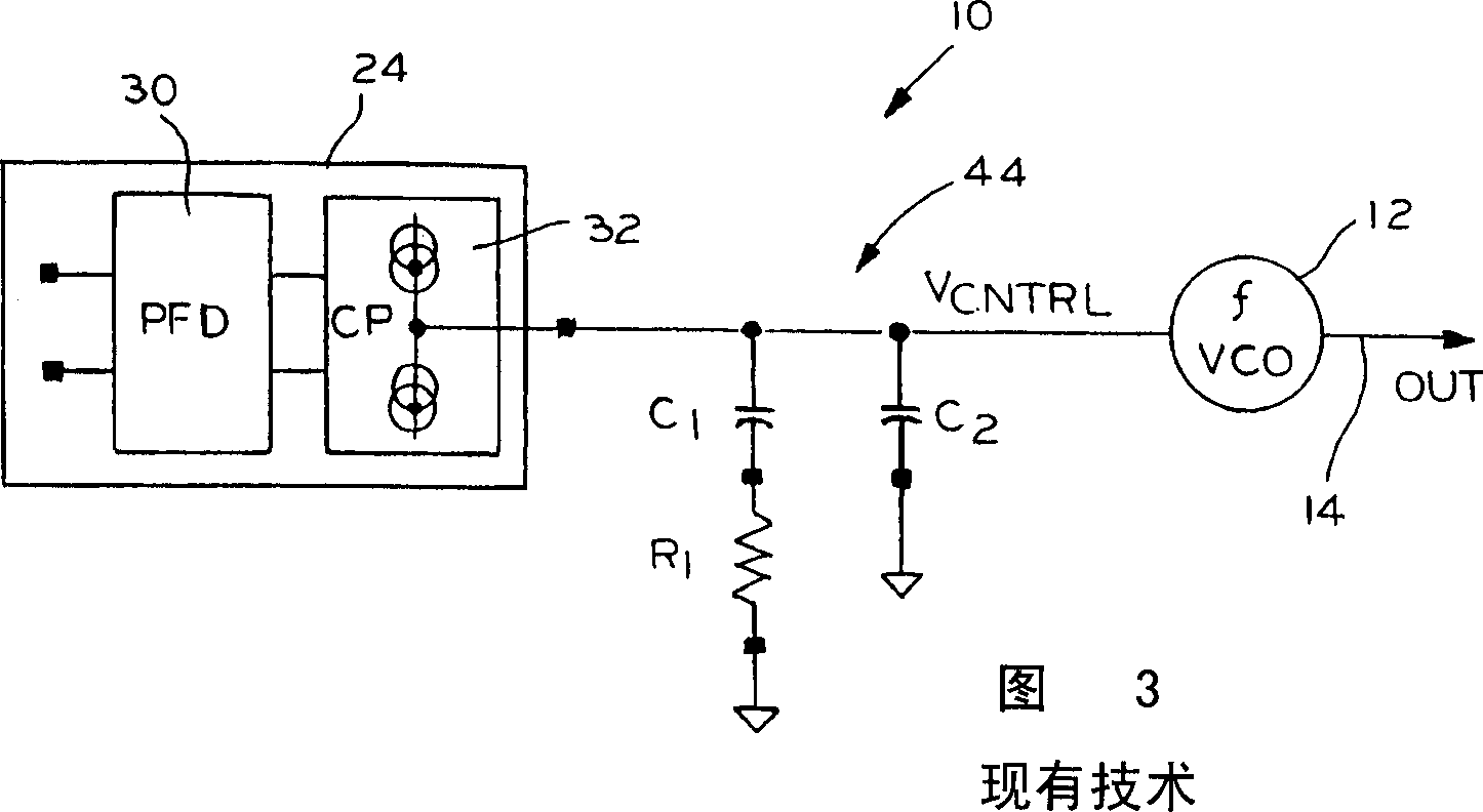
[0020] Phase detector 24 provides an output signal proportional to the phase difference of its two input signals. A loop...


PUM


Abstract

A phase-locked loop circuit with improved noise characteristics includes a voltage-controlled oscillator (12) that generates an oscillating output signal in response to a voltage-controlled input. A reference source provides a reference frequency signal. A phase detector (30) is operatively connected to said voltage controlled oscillator and a reference source to generate an output proportional to the phase difference between said oscillating output signal and the reference signal. A loop filter (46) connects the phase detector output to the voltage control input. The loop filter includes a switch-capacitor equivalent resistor (Q1, Q2, CR).

Description

Field of invention: [0001] This invention relates to phase-locked loop filter circuits, and more particularly, to loop filters with switched-capacitor resistors. Background of the invention: [0002] Phase-locked loop circuits are widely used in circuits that require the generation of high-frequency periodic signals whose frequencies are precise multiples of the frequency of some very stable low-noise reference frequency signal. The phase-locked loop circuit is also used in occasions where the phase of the output signal must track the phase of the reference signal, which is also the origin of its name "phase-locked loop". [0003] Phase-locked loop circuits are used in radio transmitters and receivers to generate local oscillator signals. This local oscillator signal is used for channel selection and is therefore a multiple of a stable, low noise and often temperature compensated reference generator. PLL circuits are also used in clock correction applications in digital co...

Claims


Application Information

Patent Timeline
Patent Type & Authority Applications(China)
IPC IPC(8): H03L7/089H03L7/093
CPCH03L7/093H03L7/0891
Inventor N·克莱默
Owner TELEFON AB LM ERICSSON (PUBL)
Why Eureka
Try Eureka