Speed reducing centrifugal duster for cleaner

A technology for centrifugal dust removal and vacuum cleaners, which is applied to suction filters, swirl devices, and devices in which the axial direction of the swirl can be reversed. and other problems, to achieve the effect of good rotation effect, small airflow pressure loss and low sound.

Inactive Publication Date: 2002-11-06
KINGCLEAN ELECTRIC
View PDF1 Cites 10 Cited by
  • Summary
  • Abstract
  • Description
  • Claims
  • Application Information

AI Technical Summary

Problems solved by technology

[0005] Since the rotating cylinder of the above-mentioned patented product is in the shape of an inverted cone, the dust is separated by the accelerated rotation of the airflow, so the pressure loss of the airflow is relatively large, which affects the dust collection effect of the vacuum cleaner.
In addition, the accelerated airflow easily lifts up the fine dust that has sunk to the bottom, and discharges it from the air outlet pipe together with the airflow, thus causing secondary pollution to the air
In addition, this product is more suitable for separating coarse particles of dust, while the separation effect for fine particles of dust is relatively poor

Method used


Image

  • Speed reducing centrifugal duster for cleaner
  • Speed reducing centrifugal duster for cleaner
  • Speed reducing centrifugal duster for cleaner

Examples


Embodiment

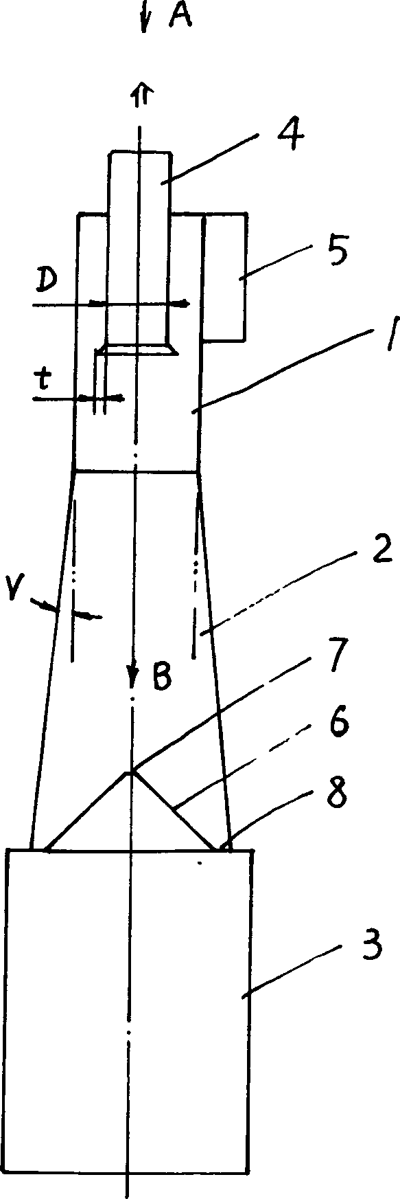
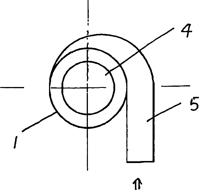
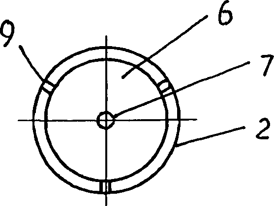
[0024] Example: as figure 1 , figure 2 , image 3 As shown in the figure, a deceleration centrifugal dust removal device for a vacuum cleaner is composed of a circular cylinder (1), a conical cylinder (2), and a dust collecting box (3) in order from top to bottom, and the top of the circular cylinder (1) extends The axis is provided with an air outlet pipe (4), the air outlet pipe (4) extends downward into the circular cylinder (1), the lower end surface of the air outlet pipe (4) is in the shape of a horn, and the circular cylinder (1) has a The outer side wall is connected with an air inlet pipe (5), and the air inlet pipe (5) at least extends the circular cylinder (1) around a 90° arc before entering the circular cylinder (1); the conical cylinder (2) It is in the shape of a small upper end and a large lower end, and the optimal range of the cone angle V is 5°--60°. The lower part of the conical cylinder (2) is provided with an umbrella-shaped reflection plate (6), and t...


PUM

PropertyMeasurementUnit
diameteraaaaaaaaaa

Abstract

The speed reducing centrifugal dusting unit of cleaner includes circular cylinder with wind outlet pipe and wind inlet pipe, conic cylinder with small upper part and large lower part, and dust collecting box connected successively from top to bottom. The conic cylinder has mushroom reflecting disc below the wind outlet pipe, and there is reflux hole in the center and ring dust-falling interval between the edge of the disc and the side wall. The unit has small pressure loss, high dust collecting effect, high dust filtering precision, low working noise and no secondary pollution; and is especially suitable for use as secondary filtering system in cleaner to separate fine dust.

Description

technical field [0001] The present invention relates to a vacuum cleaner. Background technique [0002] Existing vacuum cleaners are equipped with a filter cover or dust bag, the purpose is to filter the dirty air sucked by the vacuum motor with the filter cover or dust bag, and keep the dust particles in the dust collection tube or dust bag, so , After using the above vacuum cleaner for a period of time, the user should clean or replace the filter cover or dust bag, otherwise, the filter hole of the filter cover or dust bag will be blocked by fine dust, which will increase the dust suction resistance of the vacuum motor. In severe cases, the motor may even be burned out. Therefore, the traditional vacuum cleaner still has many deficiencies in its structure, which not only brings trouble to the user, but also affects the performance of the vacuum cleaner. [0003] In order to overcome the above shortcomings, the manufacturer applies the cyclone sepa...

Claims


Application Information

Patent Timeline
Patent Type & Authority Applications(China)
IPC IPC(8): B01D45/16B04C5/181
CPCB01D45/16B04C5/181
Inventor 倪祖根
Owner KINGCLEAN ELECTRIC
Why Eureka
Try Eureka