Photoetching method for dial of machine-tool

A dial and photolithography technology, applied in laser welding equipment, welding equipment, metal processing equipment, etc., to achieve the effect of convenient operation, long service life and high yield

Inactive Publication Date: 2002-11-27
张伟华
View PDF0 Cites 1 Cited by
  • Summary
  • Abstract
  • Description
  • Claims
  • Application Information

AI Technical Summary

Problems solved by technology

[0003] In order to overcome many problems existing in the existing dial scale method, the present invention provides a laser lithography method for machine tool dial

Method used


Image

  • Photoetching method for dial of machine-tool

Examples


Embodiment Construction

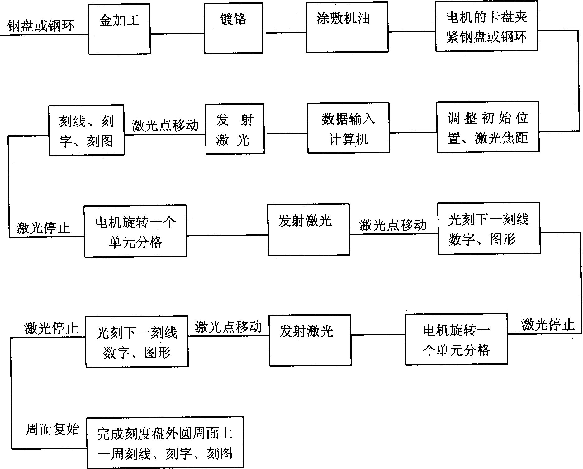
[0010] The dial blank is a steel disc or a steel ring. exist figure 1 As shown in the figure, chrome-plate the steel plate or steel ring processed by gold, apply engine oil on the outer circumferential surface of the steel plate or steel ring, and then fix it on the chuck of the motor, and adjust the initial position of the steel plate or steel ring. The position and laser focal length, the total number of divisions of the dial, the number of divisions of a cycle (the number of divisions between 2 adjacent numbers), the length of the engraved line, the size and font of numbers and graphics, and other parameters are input into the computer , the computer automatically calculates the number of pulses that control the motor to drive the dial to rotate one division (the number of pulses in a single grid = the total number of pulses that control the motor to rotate for one revolution / the number of divisions), the running distance of the laser point emitted by the laser (according t...


PUM


Abstract

A laser carving method for the dial scale of machine-tool features that after the machine oil is coated on the circumference surface of blank dial scale, the laser beam is used for carving lines, characters and graphics on the said surface while the blank dial scale is driven by a motor to rotate under the control of the computer. Its advantages are high precision, beautiful appearance, low cost,long service life and no environmental pollution.

Description

technical field [0001] The invention relates to a method for laser lithography on a dial of a machine tool. Background technique [0002] At present, the scale process of machine tool dials adopts powder casting, steel mold printing, profiling machine, and chemical corrosion methods. Low, complex process, and pollute the environment. Contents of the invention [0003] In order to overcome many problems existing in the existing dial calibration method, the invention provides a laser photolithography method for the dial of a machine tool. [0004] The technical scheme of the present invention is: coating engine oil on the outer peripheral surface of the dial plate after electroplating, and then carrying out laser marking, lettering, and pattern engraving on the outer peripheral surface of the dial plate. [0005] The computer automatically controls the motor to drive the dial to rotate and the laser point emitted by the laser to operate according to the total sub-grid, len...

Claims


Application Information

Patent Timeline
IPC IPC(8): B23K26/362
Inventor 张伟华
Owner 张伟华
Why Eureka
Try Eureka