Eureka AIR delivers breakthrough ideas for toughest innovation challenges, trusted by R&D personnel around the world.

Yarn processing system

A technology for processing systems and yarns, applied in wired transmission systems, power line communication systems, distribution line transmission systems, etc., can solve problems such as mechanical damage, DC power lines and information transmission bus cables are easily damaged, and achieve work simplification, The effect of enhancing the quality of information transmission and enhancing reliability

Inactive Publication Date: 2002-12-25
雷吉斯·穆尼奥斯
View PDF2 Cites 4 Cited by
  • Summary
  • Abstract
  • Description
  • Claims
  • Application Information

AI Technical Summary

Problems solved by technology

With a considerable number of yarn paths, DC power lines and information transmission bus cables still create a large number of damage-prone locations where mechanical damage can occur

Method used


Image

  • Yarn processing system
  • Yarn processing system
  • Yarn processing system

Examples


Embodiment Construction

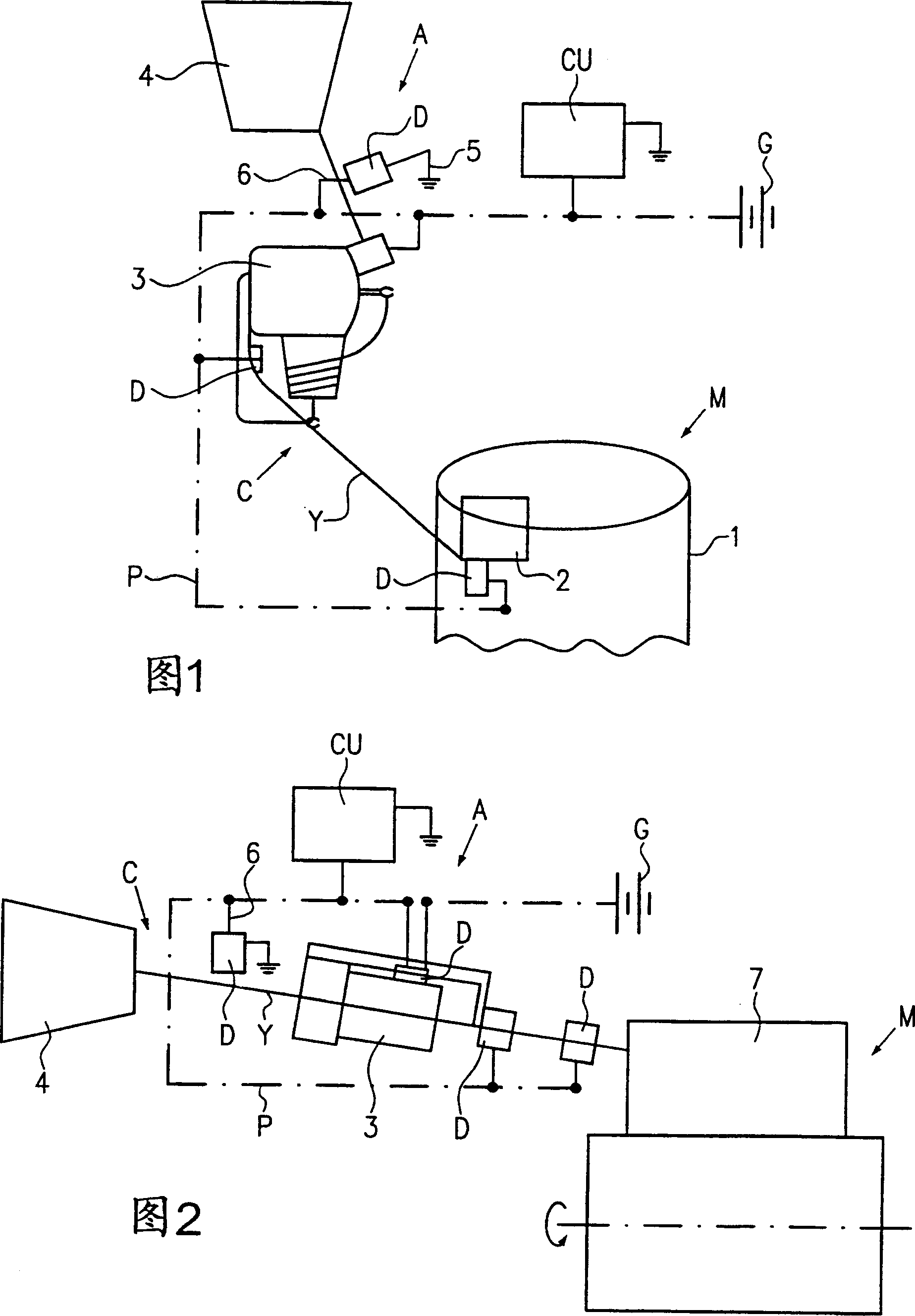
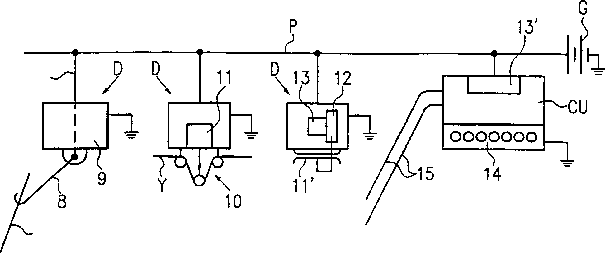
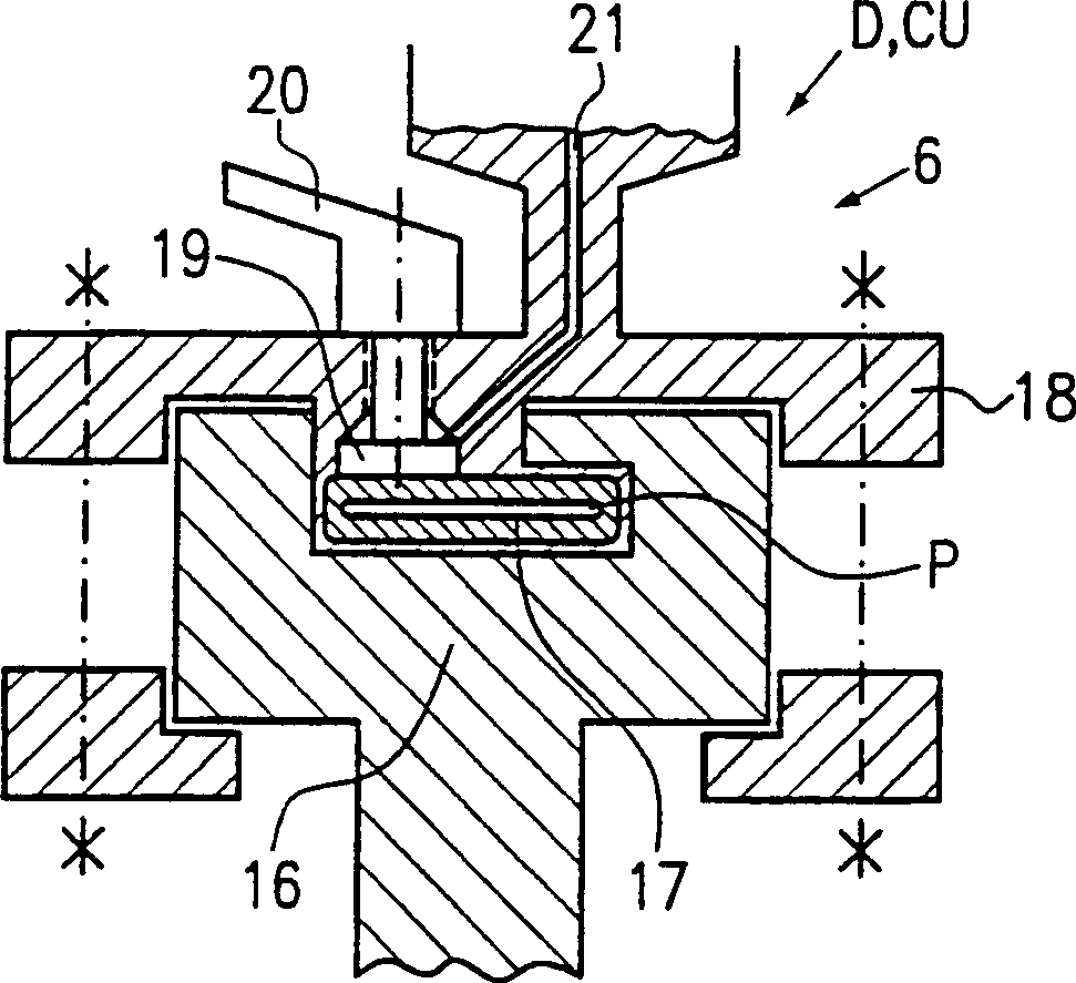
[0020] In the yarn handling system shown in the figures, a number of identical or different electrical or electronic devices are arranged along the yarn paths extending towards the individual textile machines for controlling, directly or via contact or non-contact elements, Measure, monitor, process or inspect individual yarns. When powered, the device generates a signal, or responds to a signal, and performs an operation. Some devices need to be set, eg set parameters, eg according to the desired operating behavior or the quality of the yarn. In some cases, the operation of the device must be monitored or monitored by communication. For these reasons, at least one control unit is provided. Said communication takes place by means of information representing signals, parameters, faults, measured values, etc. All devices in the network, as well as the control units, are powered by DC power from at least one DC power source. In conventional systems, separate lines are provide...


PUM


Abstract

A yarn processing system comprising a textile machine M, an accessory device A arranged along a yarn path C extending towards said textile machine M, with network participating electronics D and computerized control and monitoring of at least one control unit CU A network device, the network device has at least one DC power line connected to the device and the control unit, and an information transmission path for interconnecting the control unit and the device, the information transmission path is combined in In the common information transmission bus constituted by the conductive part 17 of the DC power line P.

Description

technical field [0001] The invention relates to a yarn processing system according to the preamble of claim 1 . Background technique [0002] In a yarn handling system known from EP 0752631 A, the well-known problem of complex cable harnesses is partly solved by using a common signal or information transfer bus for serial communication, all participants and The bus is connected. In addition, though, since each participant is connected to the DC power supply via at least one power cable, quite a few cables still have to be provided. In the yarn path of a weaving machine, such as a weaving or weaving machine, many electronic devices must be provided for detecting, measuring, monitoring, acting or reacting, for example, all in relation to the yarn being processed. Organizing the cabling arrangement is complicated by having the participants in the network and the power lines to which they are connected, and by having the signal and information transmission bus to which all the...

Claims


Application Information

Patent Timeline
IPC IPC(8): G05B19/042H04B3/54
CPCG05B19/042G05B2219/25188G05B2219/2634H04B3/548H04B2203/5441H04B2203/5458H04B2203/547H04B2203/5495
Inventor 雷吉斯·穆尼奥斯
Owner 雷吉斯·穆尼奥斯
Why Eureka
Eureka Blog
Learn More