Combine

A combine harvester and vertical axis technology, which is applied in the direction of harvesters, cutters, agricultural machinery and implements, etc., can solve the problems of enlarged setting width, inability to easily lift up the structure and manufacturing cost, and differences in harvesting straw, etc., to achieve Securing compactness, achieving manufacturing cost, and reducing weight

Inactive Publication Date: 2003-01-22
YANMAR POWER TECHNOLOGY CO LTD
View PDF0 Cites 4 Cited by
  • Summary
  • Abstract
  • Description
  • Claims
  • Application Information

AI Technical Summary

Problems solved by technology

Yet along with the difference of the place of harvesting operation or the kind of straw etc., the length of harvesting straw also obviously differs, so, long straw makes ear tip contact and lifts with driving box, easily produces straw breakage or threshing etc. In addition, when the driving box is set at a high place corresponding to the long straw, it is necessary to connect the transmission part of the lifting box and the driving box. At this time, the box of the above-mentioned transmission part protrudes to the straw conveying channel side, Straws contact the above box, the conveying posture is disturbed, the box is worn out, etc.
In addition, there is a problem that the front-rear installation width of the lift-up box and the above-mentioned input shaft becomes large by connecting the upper-side forward-leaning lift-up input shaft to the drive box provided at the high position of the upper rear-tilt lift-up box. , reducing the forward inclination angle of the above-mentioned input shaft so that the input shaft stands upright in the vertical direction can reduce the front and rear installation width, but there is a problem that the force supporting the lifting box is reduced
In this way, it is necessary to separately manufacture the raising structure of the short straw and the raising structure of the long straw, and there are some problems that the manufacturing cost reduction, weight reduction, appropriate transportation of the straw, or compactness of the raising structure cannot be easily realized.

Method used


Image

  • Combine
  • Combine
  • Combine

Examples


Embodiment Construction

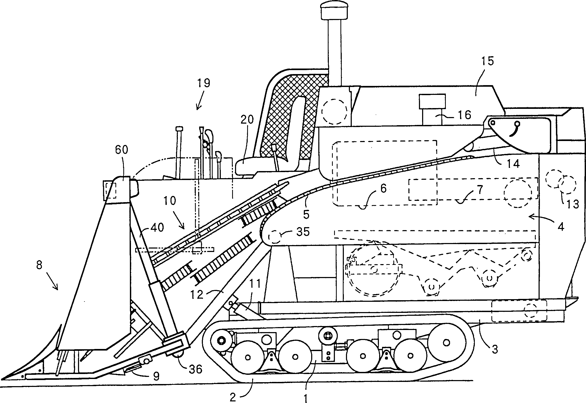
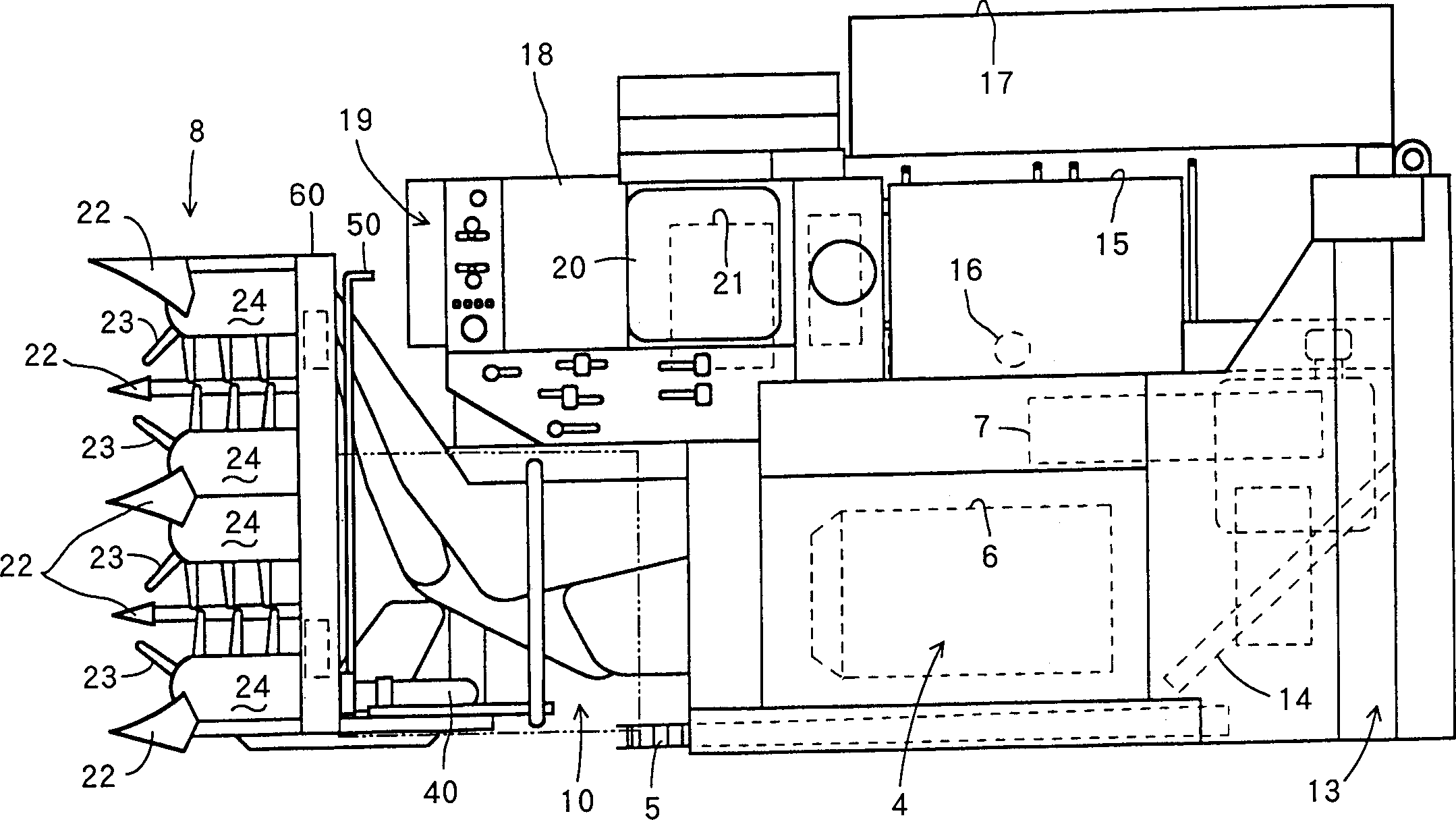
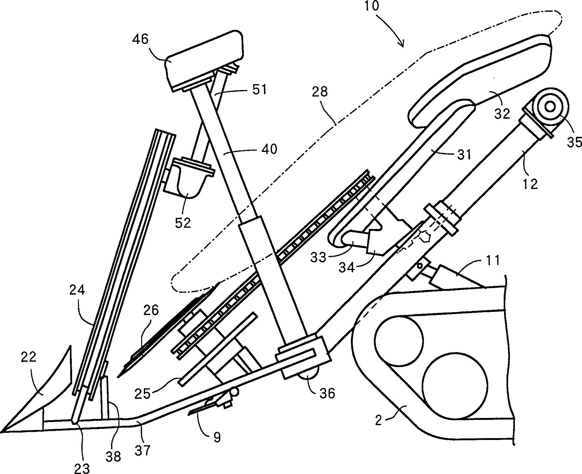
[0028] Embodiments of the present invention will be described in detail below with reference to the drawings. figure 1 For the overall left view, figure 2 for its floor plan. The symbol 1 in the figure is a crawler frame with a pair of walking crawlers 2 installed, the symbol 3 is a machine set on the upper side of the crawler frame 1, and the symbol 4 is a feed chain 5 stretched on the left side and a threshing drum 6 and a processing cylinder inside. The threshing part of 7, symbol 8 is the cutting part that has cutting knife 9 and straw conveying mechanism 10 etc., and symbol 11 is the hydraulic cylinder that makes cutting part 8 lift by cutting frame 12, and symbol 13 is facing the straw discharge chain 14 terminal straw discharge cutter, symbol 15 is the grain case that the grain from the threshing section 4 is carried in by raising the grain cylinder 16, and the symbol 17 is the grain receiving platform that the grain of the above-mentioned case 15 is carried out to th...


PUM


Abstract

A combine harvester is provided. Several pull-up cases 24 are vertically installed in the front side of a reaping unit 8, a drive case 42 for pulling up is installed in the back side of a gate 60 above each pull-up case 24 and a motive power is transmitted from the aforesaid drive case 42 to each of the aforesaid pull-up cases 24 installed with pull-up tines 23. It is characterized in that: a sprocket 44 for driving the pull-up tine is installed below a vertical shaft 54 extended from the aforesaid drive case 42, an input shaft 39 for pulling-up is connected to the drive case 42 for pulling-up through a speed change case 46 for pulling-up and the aforesaid input shaft 39 is brought to obliquely cross to the vertical shaft 54 on the side view. In this way, the backward tilting angle of a pull-up case and the forward tilting angle of an input shaft can be easily ensured, and the compaction of a structure for pulling up long cereal stems and a bearing power for pulling up by the aforesaid input shaft can be ensured.

Description

technical field [0001] The invention relates to a combine harvester for continuously cutting straw and threshing. Background technique [0002] As a prior art, for example, a plurality of lifting boxes are erected on the front side of the harvesting part, and a drive box for lifting is set on the back side of the gantry at the top of each lifting box, and power is transmitted from the driving box to the installation lifting box. The above-mentioned each of the tines lifts up the box, and then the straws that are not cut in the field are lifted by the above-mentioned tines and then it is cut. Yet along with the difference of the place of reaping operation or the kind of straw etc., the length of harvesting straw also obviously differs, so long straw makes spike tip contact with lifting box, easily produces straw breakage or threshing etc. In addition, when the driving box is set at a high place corresponding to the long straw, it is necessary to connect the transmission part...

Claims


Application Information

Patent Timeline
Patent Type & Authority Applications(China)
IPC IPC(8): A01D57/22A01D41/00
Inventor 稻垣晴三
Owner YANMAR POWER TECHNOLOGY CO LTD
Why Eureka
Try Eureka