Method and apparatus for correcting wave-front distortion in free space optical communication system

An optical communication system and free space technology, applied in the direction of free space transmission, transmission system, electromagnetic wave transmission system, etc.

Inactive Publication Date: 2003-01-29
LUCENT TECH INC
View PDF0 Cites 4 Cited by
  • Summary
  • Abstract
  • Description
  • Claims
  • Application Information

AI Technical Summary

Problems solved by technology

[0004] The present invention improves the above-menti

Method used


Image

  • Method and apparatus for correcting wave-front distortion in free space optical communication system
  • Method and apparatus for correcting wave-front distortion in free space optical communication system
  • Method and apparatus for correcting wave-front distortion in free space optical communication system

Examples


Embodiment Construction

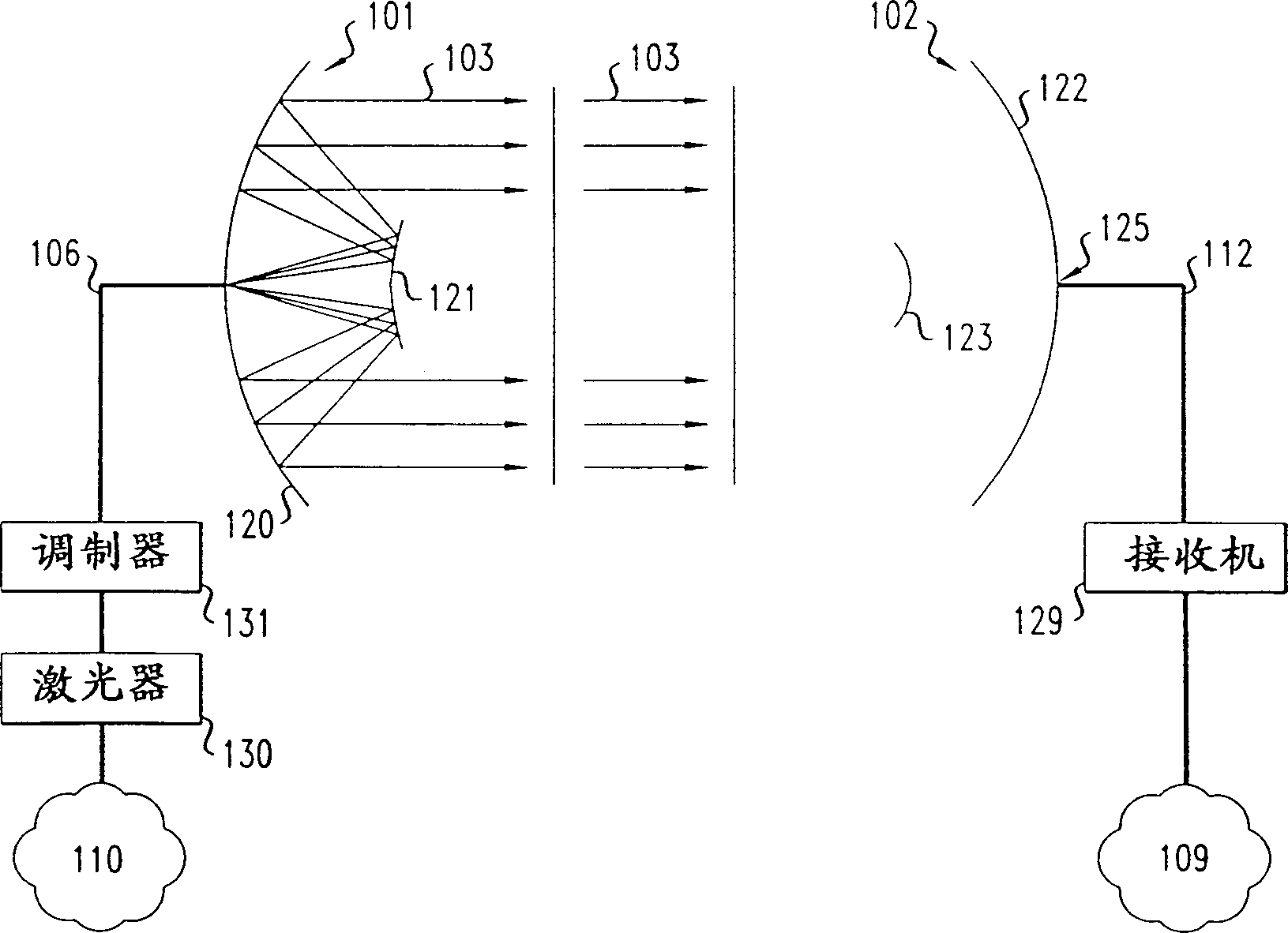
[0015] FIG. 1 shows two prior art optical communication telescopes 101 and 102 under normal alignment operating conditions in a free space optical communication system. Laser 130 produces a light beam that is modulated by modulator 131 with data received from network 110 and sent on optical fiber 106 . The transmitting telescope 101 receives the dimmed signal through the optical fiber 106 . The primary reflector 120 and the secondary reflector 121 of the telescope 101 perform optical shaping and emit a modulated beam so that the beam is incident on the focal plane 125 of the receiving telescope 102 . The receiving telescope 102 uses its optics including a primary mirror 122 and a secondary mirror 123 to focus the incident, emitted modulated light beam 103 onto the receiving optical fiber 112 at a focal plane 125 . Receiver 129 receives the modulated light signal from the receive fiber and converts it to an electrical signal, demodulates the data, and forwards the data to netw...


PUM


Abstract

A free space optical communication system is disclosed whereby the optics of a receive telescope are manipulated using adaptive optics to compensate for wave front distortion of a light beam transmitted by a transmit telescope. Wave front distortion is manifested at the receive telescope as a deviation from the normal, orthogonal orientation of the wave front of the transmitted light beam relative to its line of travel. This deviation may be detected, for example, by a wave front sensor, such as a Shack-Hartman sensor, which identifies the slope, or beam tilt, of discrete sections of the transmitted beam. The optics of the receive telescope can then be deformed in such a way as to cancel the wave front distortion and correspondingly reduce the resulting distortion of the received signal.

Description

technical field [0001] The present invention relates generally to data communication systems and, more particularly, to free space optical data communication systems. Background technique [0002] Telecommunications systems that utilize physical wires or cables to connect two or more terminals are generally limited by relatively low-speed, low-capacity applications. Laying cabling is also expensive and can be difficult for these systems, especially in congested metropolitan areas where installation options are limited. To address these limitations, some recently developed systems utilize free-space transmission of one or more light beams modulated by data to transmit data from one point to another. Free-space systems using such beams will provide higher-speed and higher-capacity links between these networks, currently up to 10Gbps, even when there is a physical, hard-wired connection between the two networks. Free space communication avoids the communication system infrast...

Claims


Application Information

Patent Timeline
IPC IPC(8): G02B26/08G02B17/00H04B10/07H04B10/11H04B10/112H04B10/118
CPCH04B10/1121
Inventor 赫曼·M·普里斯拜约翰·A·泰森
Owner LUCENT TECH INC
Why Eureka
Try Eureka