
Method for measuring weak micromagnetic field

A measurement method and magnetic field technology, applied in the measurement field of extremely weak micro-magnetic field, can solve the problems of low sensitivity, verification and leakage magnetic field measurement cannot meet the requirements, etc., and achieve the effect of high measurement sensitivity

Inactive Publication Date: 2003-02-05
SHANGHAI INST OF OPTICS & FINE MECHANICS CHINESE ACAD OF SCI
View PDF0 Cites 3 Cited by
  • Summary
  • Abstract
  • Description
  • Claims
  • Application Information

AI Technical Summary

Problems solved by technology

The main disadvantages of the above two methods are: low sensitivity, the measurement sensitivity is 1×10 -10 ~10 -12 Weber, for many special applications, such as the above-mentioned A-B effect verification and leakage field measurement cannot meet the requirements

Method used


Image

  • Method for measuring weak micromagnetic field
  • Method for measuring weak micromagnetic field

Examples


Embodiment Construction

[0023] According to the above specific method, the sample 2 to be tested is made of ferromagnetic material, and the thickness of the sample 2 to be tested is 500nm.

[0024] Take electronic hologram

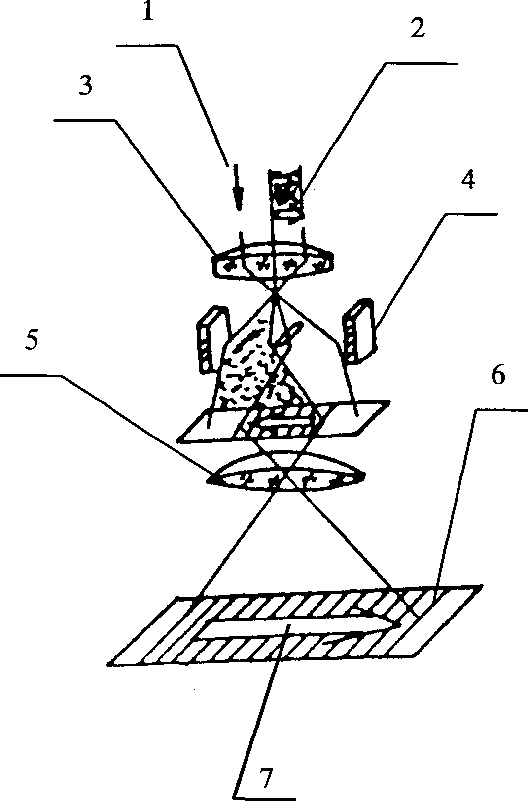
[0025] Place the above-mentioned prepared sample to be tested in such as figure 1 Electron microscopy as indicated. The electron microscope mainly includes an electron beam source 1, a sample chamber for placing a sample to be tested 2, an electromagnetic objective lens 3, an electrostatic double prism 4, a magnifying glass 5, a receiver 6 and an electronic dry plate 7 for recording electron holograms.

[0026] The electron hologram is a record of the interference pattern of the reference light and the object light, which not only requires the electron microscope to have sufficiently high spatial coherence and time coherence, but also requires the instrument to have sufficient stability. Therefore, after the electron microscope is turned on, it must be stable. After a period ...


PUM


Abstract

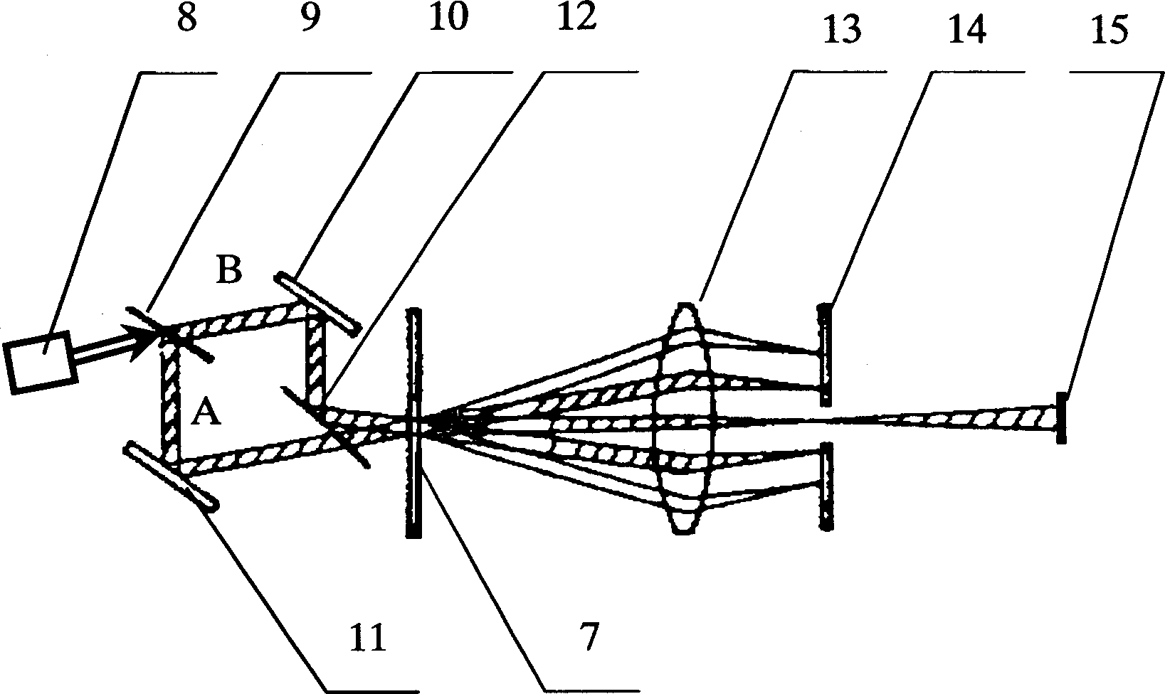
The invention relates to a method for measuring very weak magnetic field, especially the weak magnetic field with its flux less than 10 to the power -15 Wb. The sample to be tested is made from magnetic material with thickness less than or equal to 500 nano. First, the said sample is palced on the electron microscope to take electric holograph. Then, the electric photographic plate is put to the optical Mach-Rehnder interferometer for carrying out the phase difference magnification to obtain the interference pattern. The flux of the sample to be tested can be obtained by reading out the number of the interference fringe in the interference pattern. Comparing with the prior art, the invention possesses the features of high sensitivity, measuring the magnetic leakage field and very weak magnetic field as well as validating the Ahalanov-Boehm effect.

Description

Technical field: [0001] The invention relates to an extremely weak micro-magnetic field (magnetic flux less than 10 -15 Weber), especially involving electron holography for measuring weak magnetic fields. Background technique: [0002] The observation and utilization of magnetic phenomena is one of the oldest technological fields of mankind. We Chinese used the magnetic compass as far back as the third century BC, and later used it in navigation. [0003] In recent years, magnetic measurement technology has been greatly developed, and there are two main reasons for this development. (1) The needs of real life, such as the use of magnetic exploration for oil and natural gas, the study of the universe, superconducting phenomena, biomagnetic fields, etc., and the verification of the Aharanov-Bohm (abbreviated as A-B) effect; (2) the application of modern physics Achievements offer the possibility of some new measurement methods. [0004] There are two methods for weak magne...

Claims


Application Information

Patent Timeline
Patent Type & Authority Applications(China)
IPC IPC(8): G01R33/02
Inventor 陈建文高鸿奕谢红兰徐至展
Owner SHANGHAI INST OF OPTICS & FINE MECHANICS CHINESE ACAD OF SCI
Learn More