Gene chip tester

A gene chip and detector technology, applied in the field of gene chip detectors, can solve the problems of high cost, inability to observe and inspect gene chips with naked eyes, complex optical path, etc.

Inactive Publication Date: 2003-02-12
北京清大德人显微数字技术有限公司
View PDF0 Cites 3 Cited by
  • Summary
  • Abstract
  • Description
  • Claims
  • Application Information

AI Technical Summary

Problems solved by technology

The problems existing in this scanner are: 1. It cannot be used for visual observation and inspection of the gene chip; 2. The scanning of the gene chip is realized by moving the lens, which is easy to damage the microscope objective lens and affect the accuracy of the optical system; 3. Using a photomultiplier tube as the detector of the confocal optical path leads to a complex optical path and high cost

Method used


Image

  • Gene chip tester
  • Gene chip tester
  • Gene chip tester

Examples


Embodiment Construction

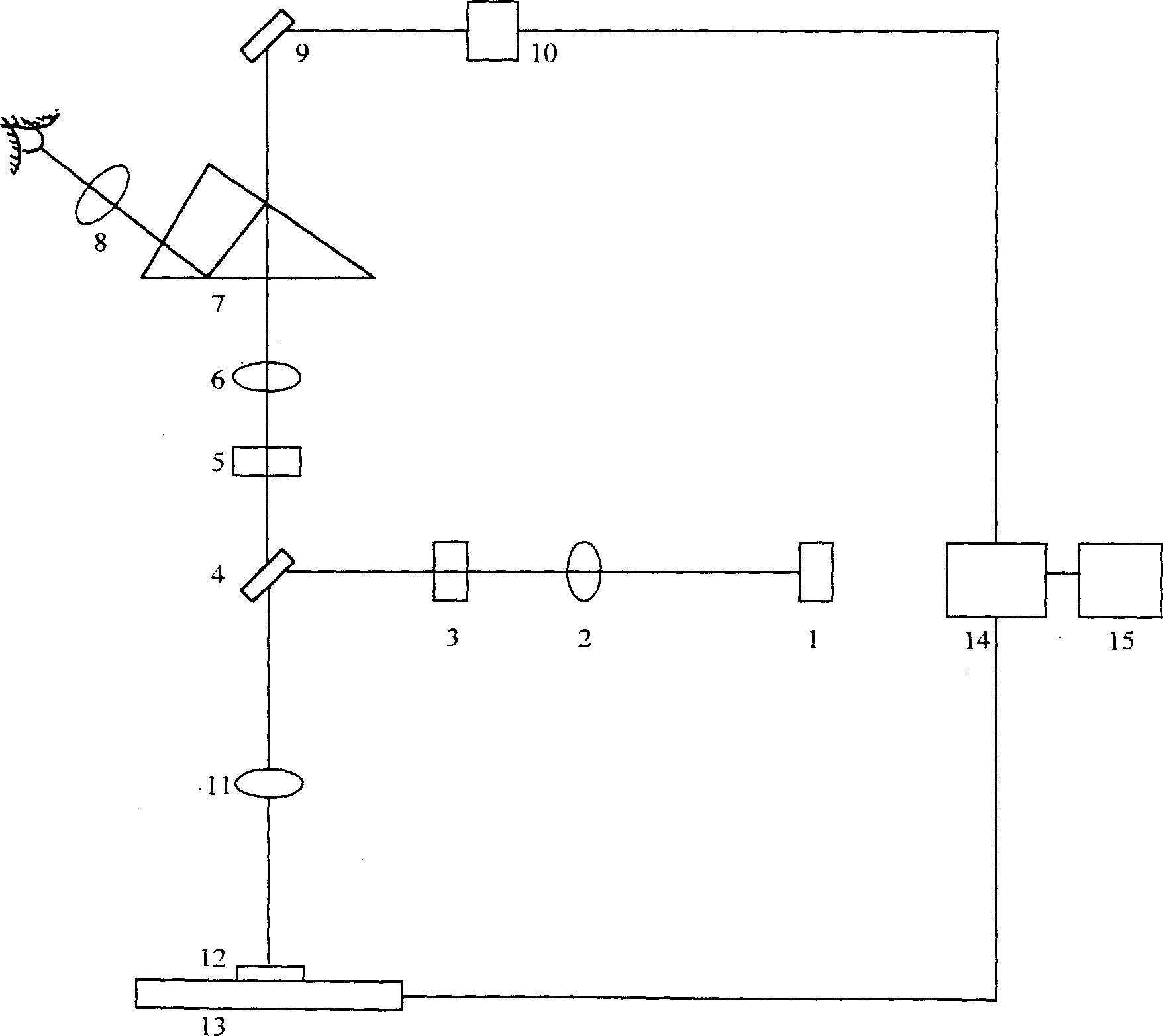
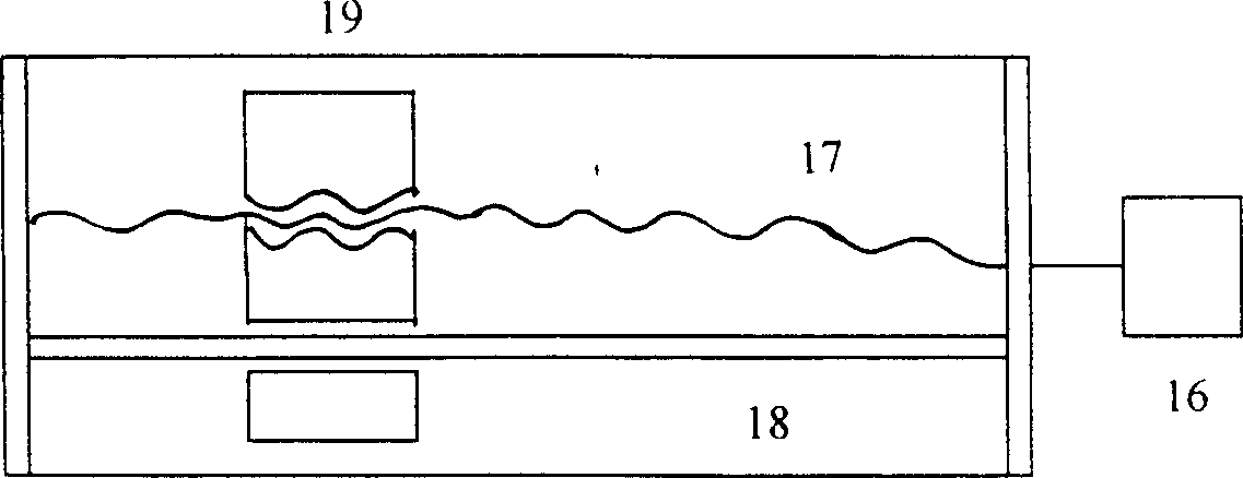
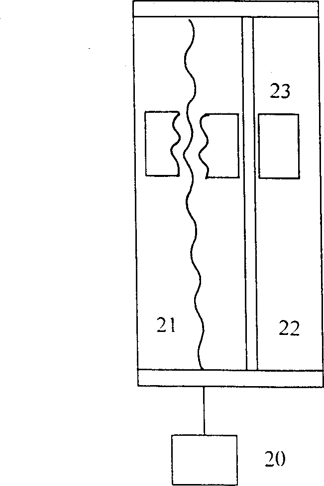
[0010] Such as figure 1 As shown, the fluorescence excitation unit of the present invention is composed of a light source 1, a lens 2, a filter 3, a mirror 4, and a microscope objective lens 11 arranged sequentially on the same optical axis. The detection unit is composed of an optical filter 5, a converging lens 6, a plane mirror 9 and a detector 10 which are sequentially set up on the same optical axis. The optical axes of the aforementioned two units intersect. The scanning unit is located below the fluorescent excitation unit and is composed of a stage 13 and a X-direction scanning moving unit and a Y-direction scanning moving unit perpendicular to each other. The Y-direction scanning mobile unit is composed of a stepping motor 20 controlled by a computer 15, a guide rail 22, a leading screw 21, and a slide block 23. The stepping motor 20 links to each other with the leading screw 21, and the guide rail 22 is arranged in parallel with the leading screw 21, and the slide b...


PUM


Abstract

A gene chip tester is composed of fluorescent exciting unit, probing unit, scan unit, A / D converter and computer for processing the signals from probing unit and A / D converter, and controlling scan unit to move in X and Y directions.

Description

technical field [0001] The invention relates to a detector, in particular to a gene chip detector. Background technique [0002] As far as the applicant knows, the latest gene chip scanner is the Model 418 laser gene chip scanner produced by the American AFFYMETRIX company. The problems existing in this scanner are: 1. It cannot be used for visual observation and inspection of the gene chip; 2. The scanning of the gene chip is realized by moving the lens, which is easy to damage the microscope objective lens and affect the accuracy of the optical system; 3. Using a photomultiplier tube as the detector of the confocal optical path leads to a complicated optical path and high cost. Contents of the invention [0003] The primary technical problem to be solved by the present invention is to realize the fast scanning of the gene chip under the condition that the optical system remains still during scanning. The quality monit...

Claims


Application Information

Patent Timeline
Patent Type & Authority Applications(China)
IPC IPC(8): C12Q1/68
Inventor 陶纯堪卞松玲高万荣杨晓春黄琳胡茂海冯海友
Owner 北京清大德人显微数字技术有限公司
Why Eureka
Try Eureka