Floor heating device and its temp. control method

A floor heating and flooring technology, which is applied in the direction of household heating, heating methods, heating systems, etc., can solve the problems of reduced heating capacity, deterioration of heat medium, and inability to purify treatment, etc., to achieve suppression of electricity bills, suppression of abnormal temperature rise, and operating costs cheap effect

Inactive Publication Date: 2003-02-12
清川晋 +1
View PDF0 Cites 16 Cited by
  • Summary
  • Abstract
  • Description
  • Claims
  • Application Information

AI Technical Summary

Problems solved by technology

[0006] In the structure in which zigzag grooves are formed on the top surface of the heat insulation board and pipes are arranged to allow the heat medium to flow through them, the heat is mainly transferred to the top of the pipes and it is impossible to conduct extensive heat laterally, and the heat cannot be fully dissipated into the room, so , there is such a constraint that the temperature of the heat medium is forced to rise to a low temperature and a high temperature
[0007] In addition, in this kind of floor heating device, due to the constraints of simply changing the flow of the heat medium and the temperature of the heat medium, there is a disadvantage that the temperature in the entire heating room cannot be quickly heated to a uniform temperature.
[0008] The second problem is that during the period from spring to autumn when the floor heating device is not needed, the heat medium does not flow in the pipe, so it cannot be purified, so the heat medium in the pipe deteriorates and generates foreign matter, and the matter If there is a blockage on the pipe, the heating performance will be completely different in the next heating time, and the heating capacity will be significantly reduced
[0044] In the conventional floor heating apparatus in which heat medium pipes are provided on insulating materials, there is a problem that, as described above, the temperature of the supply pipe produces a large difference in the discharge temperature due to the fact that the heat transfer range is limited to a narrow range, etc. , so it is difficult to control the temperature of the entire bed surface within a certain temperature

Method used


Image

  • Floor heating device and its temp. control method
  • Floor heating device and its temp. control method
  • Floor heating device and its temp. control method

Examples


Embodiment 1

[0148] The monthly electricity bills for each set temperature in Example 1 were 6,309, 4,173, and 3,165 yen, and if the daytime set temperature was lowered, the electricity bill was significantly reduced.

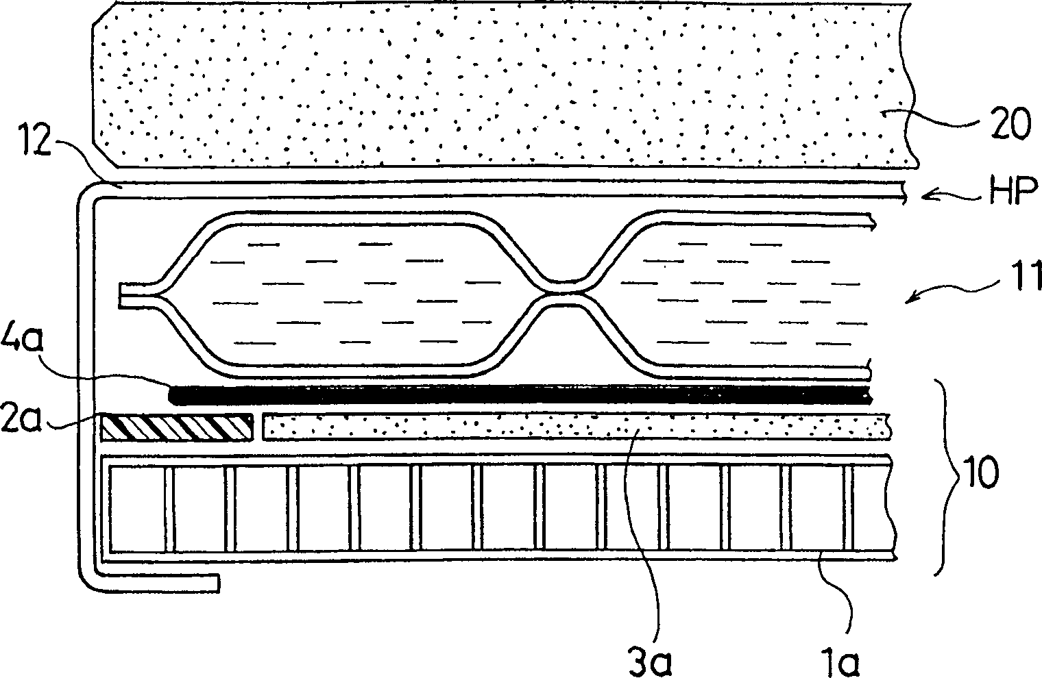
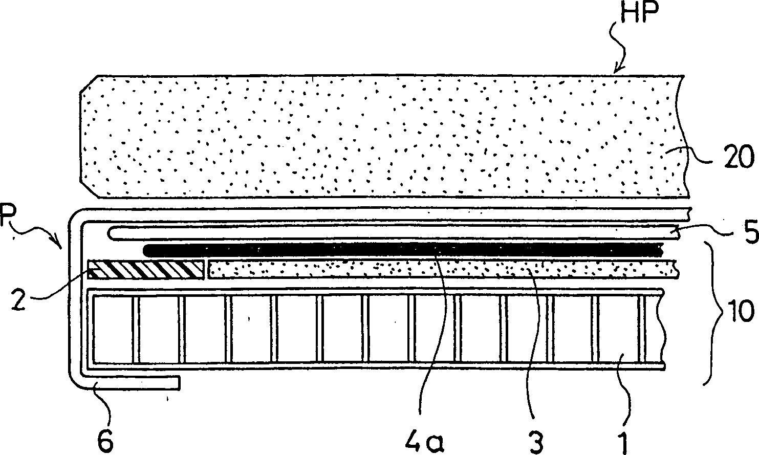
[0149] In the above-mentioned basic experiment 1, the monthly electricity bill was 16,800-11,400 yen. On the contrary, by adding sensible heat type heat storage material 20 to the heating plate P used in this basic experiment and giving a temperature difference between day and night, the temperature according to the time period was performed. control, thereby significantly reducing electricity bills as described above.

Embodiment 2

[0150] 2. Embodiment 2 (sensible heat type heat storage material)

[0151] This example uses the heating plate HP on which the same sensible heat type heat storage material 20 as in Example 1 is stacked, and shows the measured value when the average outside air temperature is 2°C in the temperature control according to the temperature difference and time interval.

[0152] time period: hours

[0153] As found in Comparative Examples 1 and 2, when the outside temperature is reduced from 13°C to 2°C, the electricity cost also increases by 40%-60%.

Embodiment 3

[0154] 3. Example 3 (latent heat type heat storage material + sensible heat type heat storage material)

[0155] This example shows measured values ​​at an average outside temperature of 13° C. in the case of using both a latent heat storage material and a sensible heat storage material as the heat storage material in the temperature difference and time period temperature control.

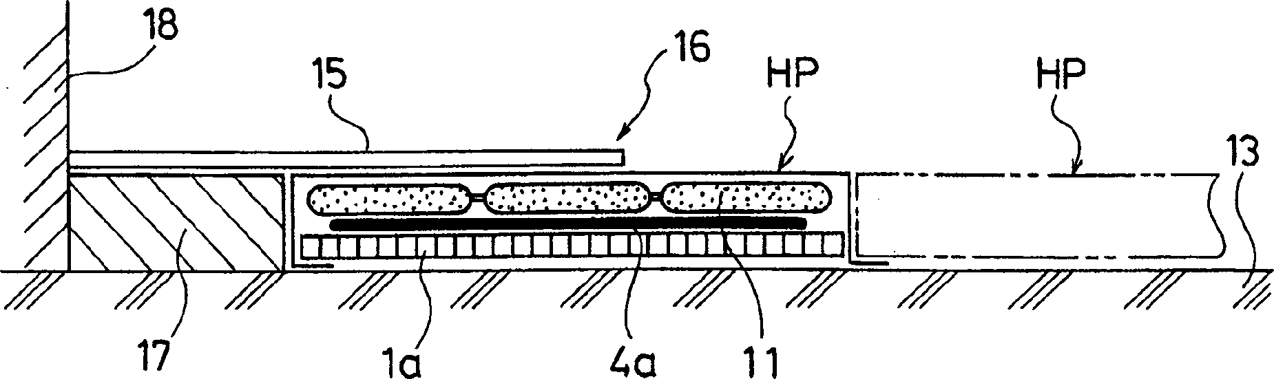
[0156] used in figure 1 Floor heating device 16 ( figure 2 ), when the average outside temperature is 13°C, divide the set temperature into 3 sections as follows, and change the setting by changing the date, and measure the power consumption at this time, the results are shown below.

[0157] time period: hours

22-8 8-22

Unit kWh Electricity charge

night day

month (yen)

Set temperature 1: °C

Power consumption 1: kWh / D

50 40

9.3 2.7

12.0 3699

Set temperature 2: ℃

Power consumption 2: kWh / D

40 30

...


PUM


Abstract

To provide a control method of temperature for a floor heating apparatus using an electric heater with a low electric bill. A heating panel HP comprises a flat plate electric power supply heating section 10 and a heat storage section 11 placed on an upper surface of the former. The heating panel HP is placed on a support floor 13 in a heating chamber. A floor finishing member 15 is laid on an upper surface of the heating panel HP, to constitute the floor heating apparatus for heating through electric power supply. The control method of temperature of the apparatus comprises the steps of dividing a power supply time zone to the heating section 10 into a daytime power supply time zone and a midnight power supply time zone, setting difference between set temperatures of the foregoing heating section 10 in these two power supply time zones, and keeping the set temperature of the midnight power supply time zone higher than that of the daytime power supply time zone.

Description

technical field [0001] The present invention relates to the improvement of the temperature control method of the floor heating device, especially to provide a method of controlling the floor heating device economically and efficiently when the electricity is turned on all day or almost 24 hours and the electricity cost is kept at a minimum. Background technique [0002] In recent years, in single-family houses and apartments, public facilities such as nursing homes, kindergartens, and public facilities, etc., floor heating devices have been used in many cases as a method of keeping indoor air clean and making full use of indoor floor heating. [0003] As the heat source of the floor heater, there are heat medium heaters such as hot water (gas heaters) and electric heaters. Therefore, the heat medium heating device forms a zigzag groove on the top surface of the insulation board and inserts a copper pipe or a synthetic resin pipe in the groove, and the heat medium heated by t...

Claims


Application Information

Patent Timeline
Patent Type & Authority Applications(China)
IPC IPC(8): F24D11/00F24D13/02
Inventor 清川晋清川太郎
Owner 清川晋
Why Eureka
Try Eureka