High-frequency amplifier and high-frequency mixer
A high-frequency amplifier and high-frequency signal technology, applied in the direction of high-frequency amplifiers, amplifiers, differential amplifiers, etc., can solve the problems of noise index degradation, base bias compensation circuit impedance reduction, etc., to suppress the degradation of noise index, reduce Current consumption, effect of increasing impedance
- Summary
- Abstract
- Description
- Claims
- Application Information
AI Technical Summary
Problems solved by technology
Method used
Image
Examples
Embodiment 1
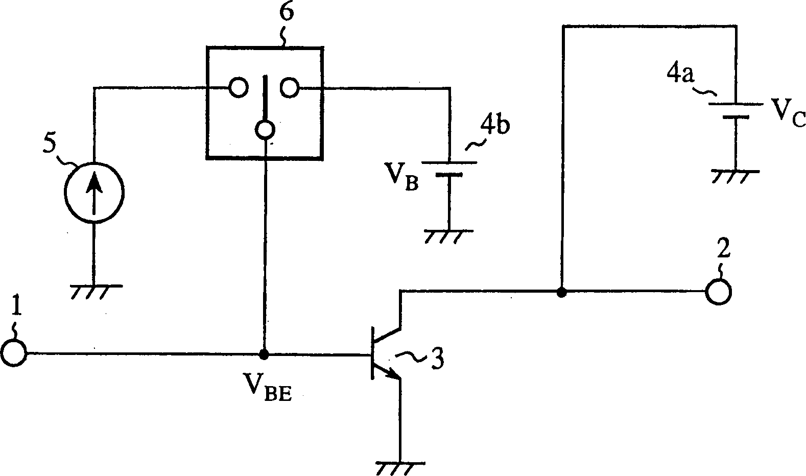
[0094] image 3 It is a circuit diagram of the high-frequency amplifier of Embodiment 1 of the present invention. In the figure, 1 is the input terminal of the high-frequency signal, 2 is the output terminal of the high-frequency signal, 3 is the bipolar transistor for amplification, 4 is the constant voltage source, 5 is the constant current source, and 6 is used to switch the constant voltage source 4b and the switching switch of the constant current source 5.
[0095] The structure is described below.
[0096] According to the high-frequency amplifier of Embodiment 1, the emitter is grounded and the amplifying bipolar transistor 3 is used, corresponding to the power level of the high-frequency signal input to the amplifying bipolar transistor 3 or the power level of the output high-frequency signal, The constant current source 5 and the constant voltage source 4 b are respectively switched to apply a DC bias to the base terminal of the bipolar transistor 3 for amplificati...
Embodiment 2
[0101] Figure 4 is a circuit diagram of a high-frequency amplifier according to Embodiment 2 of the present invention. In the figure, 1 is the input terminal of the high-frequency signal, 2 is the output terminal of the high-frequency signal, 3 is the bipolar transistor for amplification, 4 is the constant voltage source, 5 is the constant current source, and 6 is used to switch the constant voltage source 4b and the switching switch of the constant current source 5.
[0102] The structure is described below.
[0103] According to the high-frequency amplifier of Embodiment 2, the emitter is grounded and the amplifying bipolar transistor 3 is used, corresponding to the power level of the high-frequency signal input to the amplifying bipolar transistor 3 or the power level of the output high-frequency signal, The constant current source 5 and the constant voltage source 4b are respectively switched to apply a DC bias to the base terminal of the amplifying bipolar transistor 3...
Embodiment 3
[0108] Figure 5 is a circuit diagram of a high-frequency amplifier according to Embodiment 3 of the present invention. In the figure, 1 is the input terminal of the high-frequency signal, 2 is the output terminal of the high-frequency signal, 3 is the bipolar transistor for amplification, 4 is the constant voltage source, 5 is the constant current source, and 6 is used to switch the constant voltage source 4b and the switching switch of the constant current source 5, 7 is a bias resistor.
[0109] The structure is described below.
[0110] According to the high-frequency amplifier of the third embodiment, the emitter is grounded and the amplifying bipolar transistor 3 is used, corresponding to the power level of the high-frequency signal input to the amplifying bipolar transistor 3 or the power level of the output high-frequency signal, Switch to the constant current source 5 and the constant voltage source 4b respectively to apply a DC bias to the base terminal of the bipo...
PUM
 Abstract
Description
Claims
Application Information
 - R&D
- Intellectual Property
- Life Sciences
- Materials
- Tech Scout
- Unparalleled Data Quality
- Higher Quality Content
- 60% Fewer Hallucinations
Browse by: Latest US Patents, China's latest patents, Technical Efficacy Thesaurus, Application Domain, Technology Topic, Popular Technical Reports.
© 2025 PatSnap. All rights reserved.Legal|Privacy policy|Modern Slavery Act Transparency Statement|Sitemap|About US| Contact US: help@patsnap.com


