

Cyclone-type sucking-exhausting mechanism
A mechanical device and a swirl-type technology, which is applied in the field of swirl-type suction and exhaust mechanical devices, can solve problems such as potential safety hazards, corrosion of fans, and increased costs, and achieve the effects of stable performance, simple manufacture, and reasonable structural design
- Summary
- Abstract
- Description
- Claims
- Application Information
AI Technical Summary
Problems solved by technology
Method used
Image

Examples
Embodiment 1
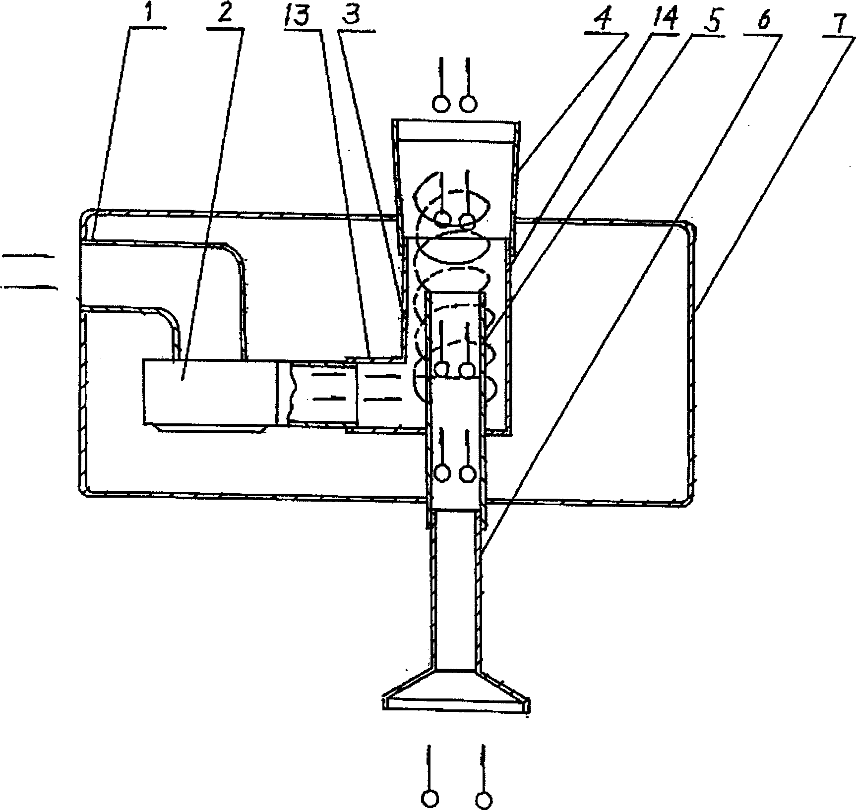
[0030] An air outlet at one end of the air collecting tube (1) is fixedly connected with an air inlet at one end of the fan (2), and the air collecting tube (1) is cylindrical. The air outlet at the other end of the blower fan (2) is fixedly connected with the air inlet tube (13) of the cyclone (3). The fan (2) blows the clean air into the cyclone (3) through the air collector (1), so that the clean air rotates in the cyclone (3), forming a rotating air flow, which is uniform along the inner wall of the cyclone (3). The flow direction rotates and rotates around the axis of the cylindrical body to the outlet end, and the rotating air flow forms a low-pressure core at the outlet end of the air inlet cylinder (5), generating suction force. The air outlet (14) of the swirler (3) is fixedly connected with the air inlet of the exhaust air duct (4), and the exhaust air duct (4) is a tubular gradual expansion shape, and the exhaust air duct (4) The end of the exhaust outlet is placed...
Embodiment 2
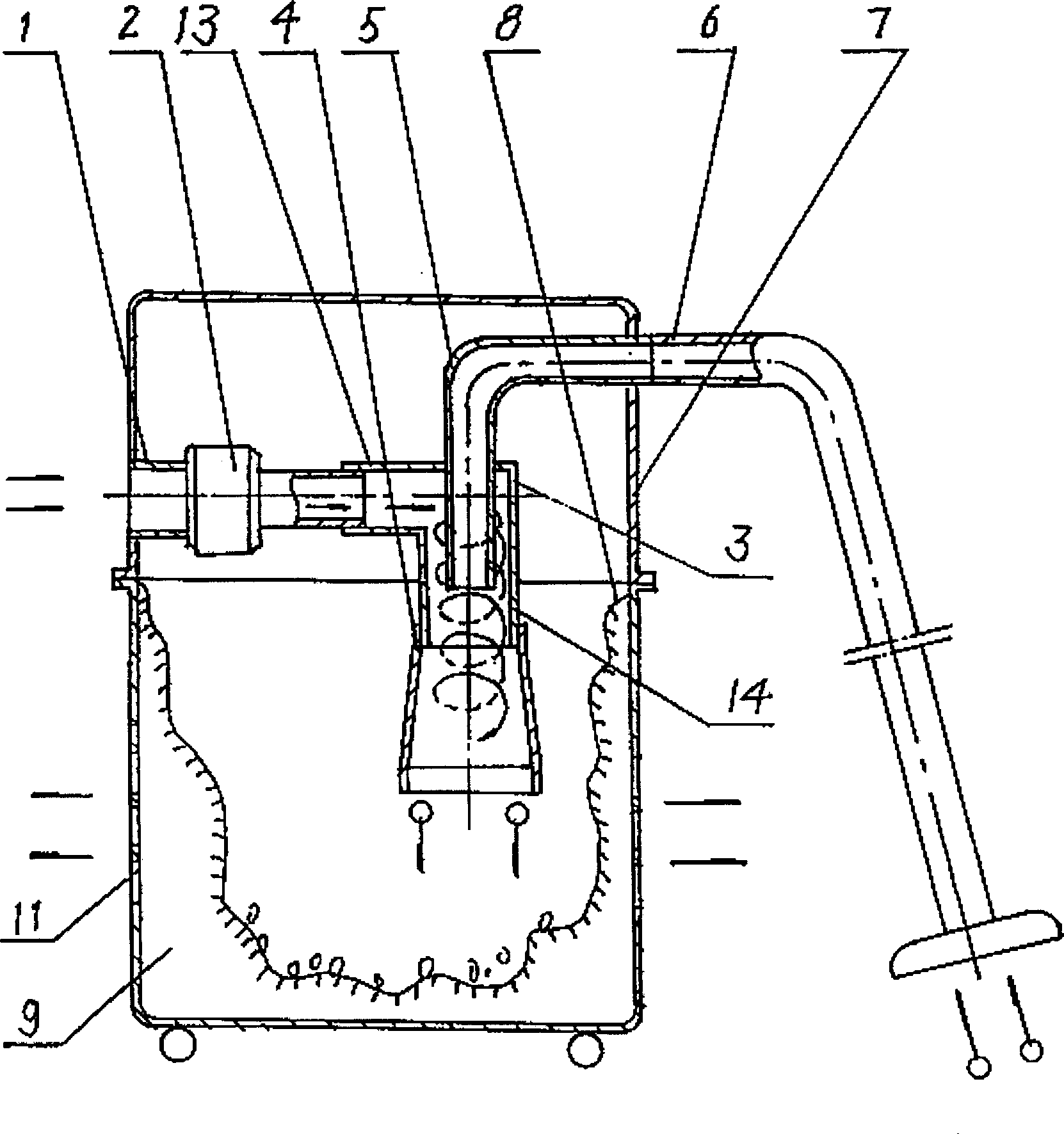
[0033]One end of the air collecting tube (1) is fixedly connected with the air inlet at one end of the fan (2), and the air collecting tube (1) is cylindrical. The air outlet at the other end of the blower fan (2) is fixedly connected with the air inlet tube (13) of the cyclone (3). The fan (2) blows the clean air into the cyclone (3) through the air collector (1), so that the clean air rotates in the cyclone (3), forming a rotating air flow, which is uniform along the inner wall of the cyclone (3). The flow direction rotates and rotates around the axis of the cylindrical body to the outlet end, and the rotating air flow forms a low-pressure core at the outlet end of the air inlet cylinder (5), generating suction force. The air outlet tube (14) of the swirler (3) is fixedly connected with the air inlet of the exhaust air tube (4), and the exhaust air tube (4) is a cylindrical gradually expanding shape. A dust collection chamber (9) is arranged at the exhaust outlet end of the...
Embodiment 3
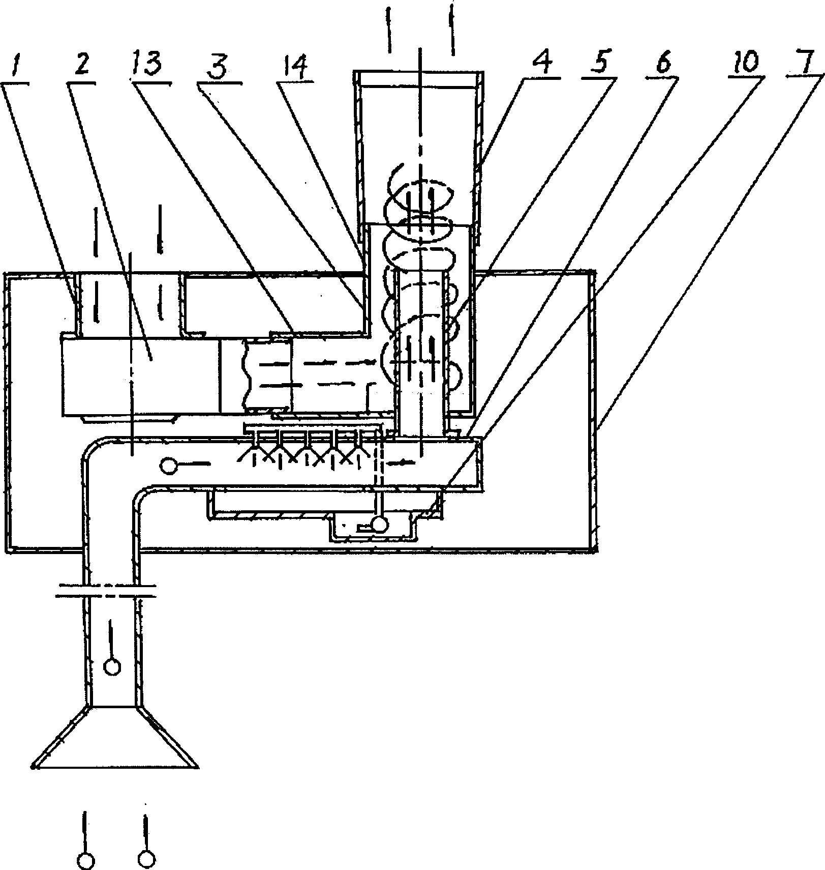
[0036] One end of the air collecting tube (1) is fixedly connected with the air inlet at one end of the fan (2), and the air collecting tube (1) is cylindrical. The air outlet at the other end of the blower fan (2) is fixedly connected with the air inlet tube (13) of the cyclone (3). The fan (2) blows the clean air into the cyclone (3) through the air collector (1), so that the clean air rotates in the cyclone (3), forming a rotating air flow, which is uniform along the inner wall of the cyclone (3). The flow direction rotates and rotates around the axis of the cylindrical body to the outlet end, and the rotating air flow forms a low-pressure core at the outlet end of the air inlet cylinder (5), generating suction force. The air outlet (14) of the swirler (3) is fixedly connected with the air inlet of the exhaust air duct (4), and the exhaust air duct (4) is a tubular gradual expansion shape, and the exhaust air duct (4) The end of the exhaust outlet is placed outside the cas...
PUM
 Abstract
Description
Claims
Application Information