
A/D converter circuit

A digital conversion, analog converter technology, applied in the direction of analog to digital converter, reconfigurable analog/digital converter, etc., to achieve high conversion accuracy, increase the complexity and circuit scale, and increase the degree of freedom of design.

Inactive Publication Date: 2003-02-26
TESSERA ADVANCED TECH
View PDF4 Cites 10 Cited by
  • Summary
  • Abstract
  • Description
  • Claims
  • Application Information

AI Technical Summary

Problems solved by technology

[0130] In the above-mentioned conventional analog-to-digital conversion circuit, when the voltage range of the analog input signal changes, or when the input method of the analog input signal changes, the circuit configuration must be redesigned.

Method used


Image

  • A/D converter circuit
  • A/D converter circuit
  • A/D converter circuit

Examples


Embodiment Construction

[0238] (1) First Embodiment

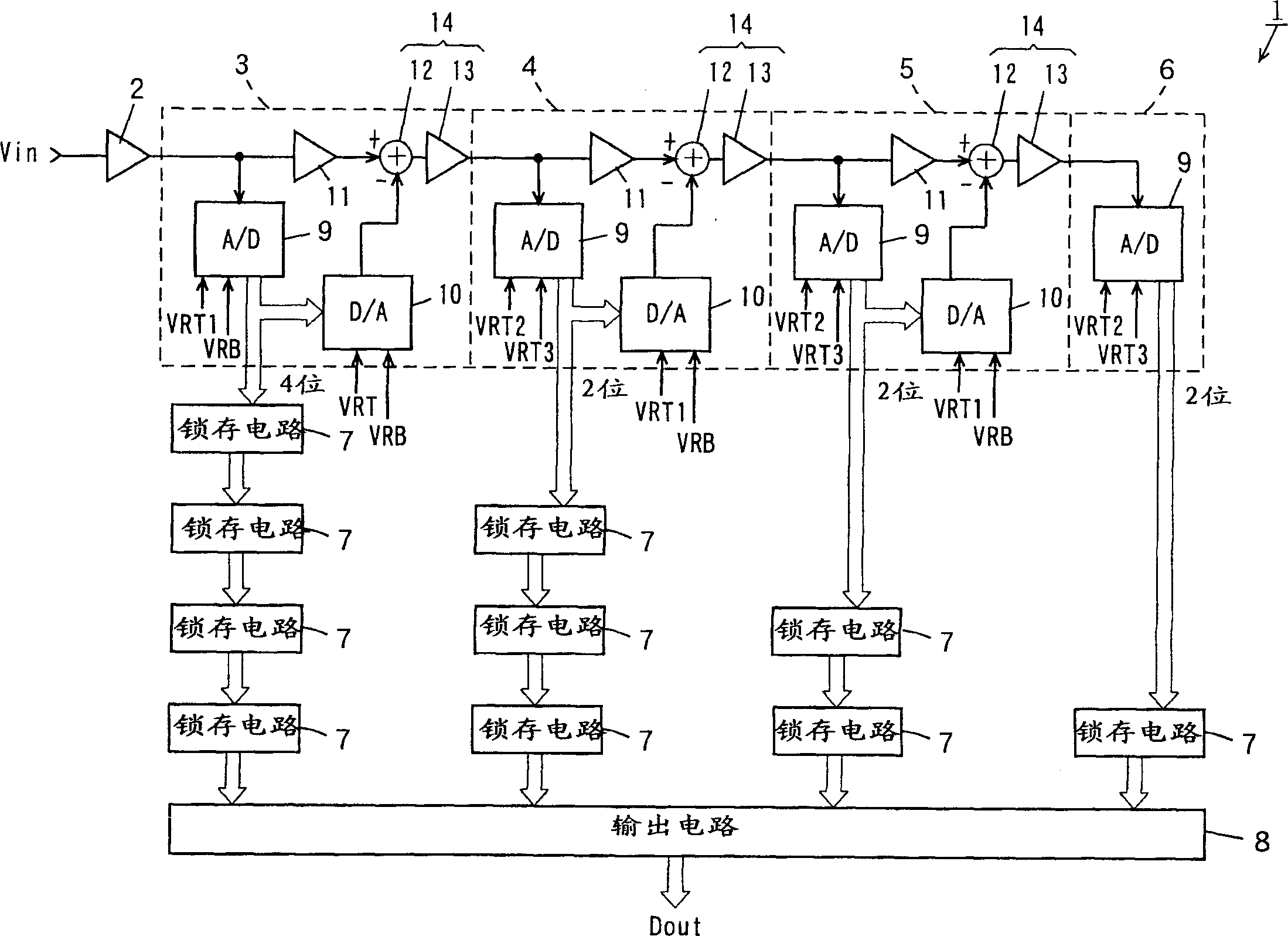
[0239] figure 1 Shown is a block diagram of the configuration of the analog-to-digital conversion circuit according to the first embodiment of the present invention. figure 1 The analog-to-digital conversion circuit 1 has a 10-bit 4-stage pipeline structure.

[0240] exist figure 1 Among them, the analog-to-digital conversion circuit 1 is composed of a sample-and-hold circuit 2, a first-stage-fourth stage circuit 3-6, a plurality of latch circuits 7, and an output circuit 8.

[0241] The circuits 3 , 4 , and 5 of the first stage (initial stage) to the third stage include a sub-A / D converter 9 , a D / A converter 10 , an operational amplifier circuit 11 , a subtraction circuit 12 , and an operational amplifier circuit 13 . The subtraction circuit 12 and the operational amplifier circuit 13 constitute a subtraction amplifier circuit (differential amplifier) ​​14 . The gain of the operational amplifier circuits 11 and 13 in the first to third st...


PUM


Abstract

This invention discloses an analog-to-digital conversion circuit, the gain of an operational amplification circuit in each of first- to third-stage circuits is two. The reference voltage range of a sub-A / D converter in each of the stages of circuits is set to one-half the reference voltage range of a D / A converter, so that the output voltage range of the D / A converter coincides with the output voltage range of the operational amplification circuit. When the voltage range of the analog input signal is VIN[p-p], the full-scale range of the sub-A / D converter is switched to VIN[p-p], and the gain of the operational amplification circuit is one. When the voltage range of the analog input signal is VIN[p-p] / 2, the full-scale range of the sub-A / D converter is switched to VIN[p-p] / 2, and the gain of the operational amplification circuit is two.

Description

technical field [0001] The invention relates to an analog-to-digital conversion circuit with a multi-stage pipeline (hierarchical flashing) structure. Background technique [0002] In recent years, with the advancement of digital processing technology for video signals, the demand for analog-to-digital conversion circuits (A / D converters) for video signal processing has increased. action, so in the past widely used 2-stage flashing (2-stage parallel) method. [0003] However, as the number of conversion bits (bits) increases, sufficient conversion accuracy cannot be obtained by using the 2-stage flicker method, so an analog-to-digital conversion circuit with a multi-stage pipeline (hierarchical flicker) structure has been developed. [0004] Fig. 38 is a block diagram showing the configuration of a conventional analog-to-digital conversion circuit having a multi-stage pipeline structure. The analog-to-digital conversion circuit shown in FIG. 38 has a 10-bit four-stage pipe...

Claims


Application Information

Patent Timeline
Patent Type & Authority Applications(China)
IPC IPC(8): H03M1/18
CPCH03M1/18H03M1/004
Inventor 二改教广和田淳谷邦之木村安行加藤健一
Owner TESSERA ADVANCED TECH
Learn More