Solid electrolytic capacitor and its manufacture

A technology of solid electrolysis and capacitors, which is applied in the direction of solid electrolytic capacitors, electrolytic capacitors, capacitors, etc., to achieve the effects of excellent joint strength and reliability, stable welding operations, and improved equivalent series resistance characteristics

Inactive Publication Date: 2003-03-05
PANASONIC CORP
View PDF0 Cites 6 Cited by
  • Summary
  • Abstract
  • Description
  • Claims
  • Application Information

AI Technical Summary

Problems solved by technology

Therefore, a part of the dielectric vaporized film layer 56 formed on the anode portion 59 is cracked along with the bending deformation, and destruction occurs in accordance with this, and a serious phenomenon of leakage current (LC) occurs.

Method used


Image

  • Solid electrolytic capacitor and its manufacture
  • Solid electrolytic capacitor and its manufacture
  • Solid electrolytic capacitor and its manufacture

Examples


Embodiment approach 1

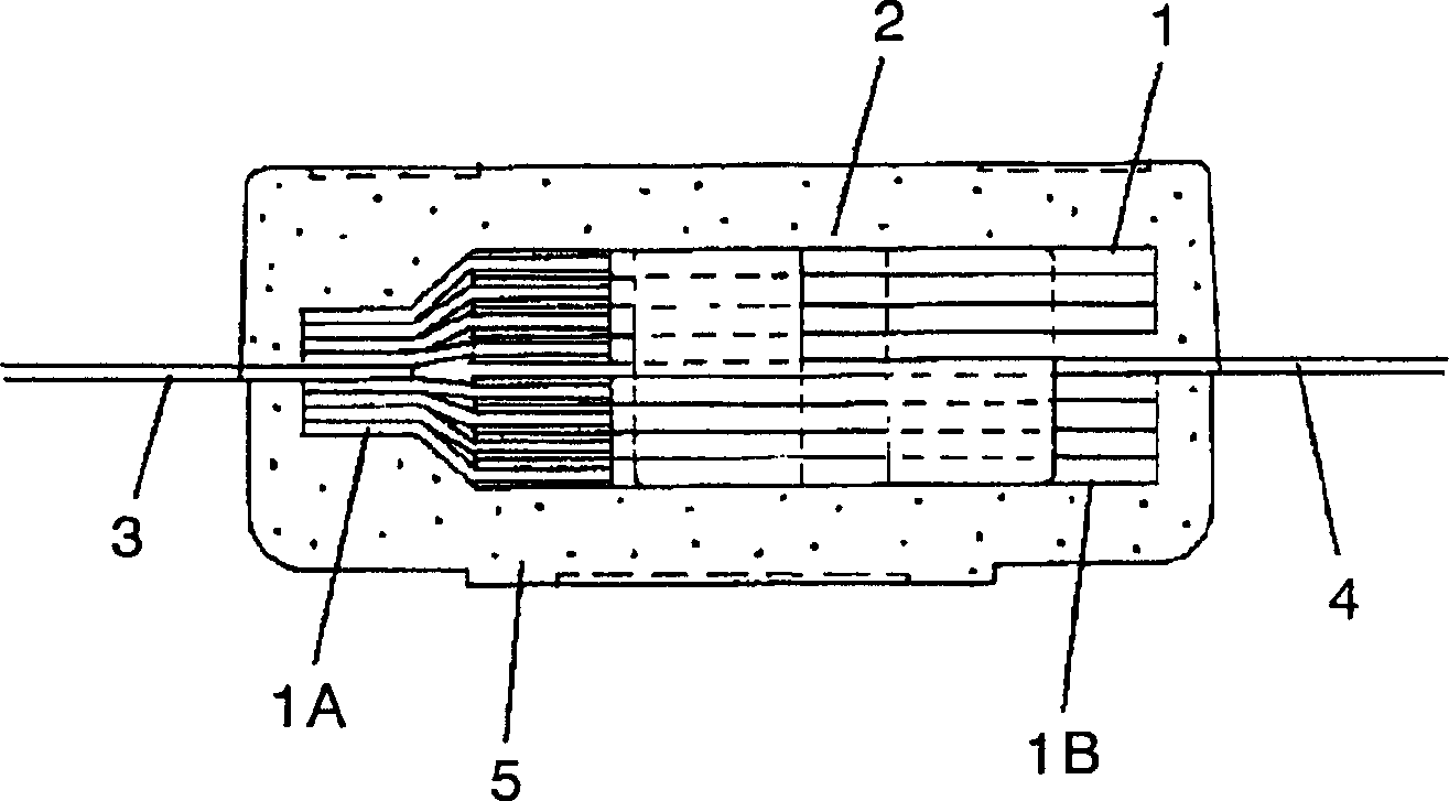
[0077] Mainly used below figure 1 and figure 2 Embodiment 1 will be described.

[0078] Capacitor element (hereinafter referred to as element) 1 separates the anode body composed of valve metal, i.e. aluminum foil, into an anode part 1A and a cathode part, and is composed of a dielectric oxide film layer and a solid electrolyte layer formed by sequential lamination on the surface of the cathode part 1B. layer, cathode tube (not shown).

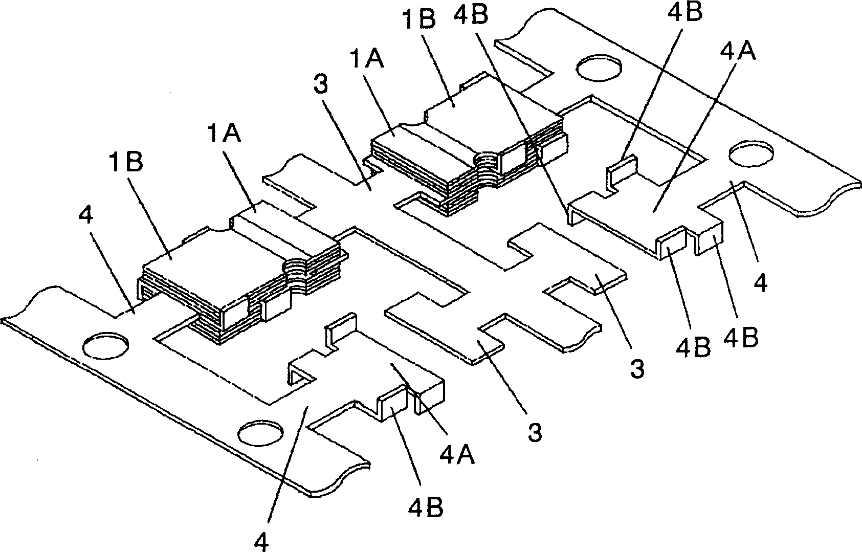
[0079] A capacitor element stack (hereinafter referred to as a stack) 2 is connected to an anode lead frame 3 and a cathode lead frame 4 after stacking a plurality of elements 1 . This structure will be described in more detail below. The anode part 1A of the element 1 is arranged on the front and back of the anode lead frame 3, and the cathode part 1B is arranged on the front and back of the cathode lead frame, respectively, and then stacked one by one. Next, the respective anode parts 1A are integrally bonded to the anode lead frame 3 b...

Embodiment approach 2

[0093] Embodiment 2 differs from Embodiment 1 in the shapes of the anode lead frame and the cathode lead frame, but is the same as Embodiment 1 except that. use below Figure 4 and Figure 5 Only the different parts are described.

[0094] A plurality of capacitive element parts 1A are disposed on one surface of the anode lead frame 6 and stacked one by one, and a plurality of cathode parts 1B are disposed on the front and back of the cathode lead frame 7 and stacked one by one. Each anode part 1A is integrally joined to each anode lead frame 61 by laser welding. In addition, the respective cathode portions are electrically bonded integrally at the connection portion 7B provided on the cathode lead frame 7 on the side surface in the thickness direction of the capacitor element 1 through conductive silver paste (not shown). In addition, the connecting portion 7B is formed in advance by bending a part of both ends of the planar portion 7A of the cathode lead frame 7 . In add...

Embodiment approach 3

[0097] This third embodiment is an example in which the shape of the cathode lead frame in the above-mentioned embodiment 1 is different, and the configuration is the same as that of the first embodiment except that, and the following uses Figure 6 , Figure 7 Only the different parts are described.

[0098] Cathode lead frame 8 has connection portion 8A and holding portion 8B formed by bending a part of cathode lead frame 8 .

[0099] The connecting portion 8A is formed so as to be located on the opposite side of the anode portion 1A of the capacitor element stack 2 . Then, the respective cathode portions 1B of the capacitor element 1 are integrally connected on the side surfaces in the thickness direction of the capacitor element 1 through the conductive silver paste 9 . In addition, the holding portion 8B holds the upper and lower surfaces of the capacitor element stack 2 .

[0100] The solid electrolytic capacitor in the third embodiment configured in this way has the ...


PUM

PropertyMeasurementUnit
Electrostatic capacitanceaaaaaaaaaa

Abstract

Provided is a solid electrolytic capacitor and manufacturing method thereof which facilitates an assembly work with simple construction to lead to a reduction of cost, realizes excellent equivalent series resistance characteristics and makes a thin configuration possible. With the solid electrolytic capacitor of the present invention, a cathode lead frame has a connecting member to connect integrally with a cathode member of a capacitor element stack body on the side surface of a capacitor element extending in the thickness direction thereof. Capacitor elements, each provided with a through hole on an anode member, are stacked on top of each other in layers and connections between capacitor elements are achieved by disposing an anode lead frame between layers. Accordingly, when a plurality of anode members are joined to the anode lead frame via a through hole provided on respective anode members of capacitor elements, stabilized welding work is allowed to be performed without any of molten aluminum foil to be released outside.

Description

technical field [0001] The present invention relates to a solid electrolytic capacitor used in various electronic devices and a manufacturing method. Background technique [0002] exist Figure 30 A perspective view representing the composition of a prior art solid electrolytic capacitor is shown in Figure 31 A perspective view showing the constitution of a solid electrolytic capacitor element laminate is shown in . exist Figure 30 , Figure 31 Among them, the capacitor element 50 is constituted by separating an anode body made of aluminum foil, which is a valve-acting metal, into an anode portion 50A and a cathode portion 50B. Furthermore, an oxide film layer, a solid electrolyte layer, and a cathode layer (none of which are shown) are sequentially stacked on the surface of the cathode portion 50B. [0003] The capacitor element stack assembly 51 is constructed in the following manner: [0004] 1A) Cathode portion 50B is joined by applying conduct...

Claims


Application Information

Patent Timeline
IPC IPC(8): H01G9/00H01G9/012H01G9/15
CPCH01G9/26H01G9/15H01G9/012
Inventor 只信一生杉本尊央岳幸博小岛逸男川原一也田制正俊薮下正弘
Owner PANASONIC CORP
Why Eureka
Try Eureka