
Bearing structure of drive shaft for ship

A technology for drive shafts and ships, applied in the field of bearing construction, can solve problems such as temperature rise in the bearing chamber 6, troublesome maintenance work, grease leakage, etc., and achieve the effect of reducing frequency, reducing frequency, and preventing excessive deformation

Inactive Publication Date: 2003-03-26
HONDA MOTOR CO LTD
View PDF1 Cites 6 Cited by
  • Summary
  • Abstract
  • Description
  • Claims
  • Application Information

AI Technical Summary

Problems solved by technology

[0012] However, according to such a conventional bearing structure, there is a problem that the temperature rise in the bearing chamber 6 and the resulting expansion of the grease and air in the bearing chamber 6 cause the grease in the bearing chamber 6 to leak out of the bearing chamber 6.
[0013] Usually, a ship repeats its running and stopping, thereby causing the temperature of the bearing chamber 6 to rise and fall (thus the expansion and contraction of the grease and air in the bearing chamber 6) repeatedly, and the air enters the bearing from a minute gap when the temperature drops. In the chamber 6, when the temperature rises, it expands again, and the grease is pushed out of the bearing chamber 6. Therefore, in the existing bearing structure, the grease in the bearing chamber 6 is lost in a short period of time due to the repeated running and stopping of the ship. reduced problem
[0014] For this reason, in the existing bearing structure, it may be necessary to fill the bearing chamber 6 with grease at short intervals depending on the running conditions of the ship, and there is a problem that the maintenance work is very troublesome.

Method used


Image

  • Bearing structure of drive shaft for ship
  • Bearing structure of drive shaft for ship
  • Bearing structure of drive shaft for ship

Examples


Embodiment Construction

[0051] Embodiments of the present invention will be described below with reference to the drawings.

[0052] (first embodiment)

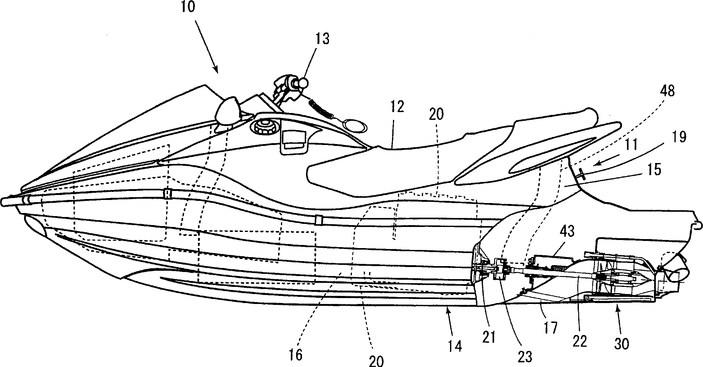
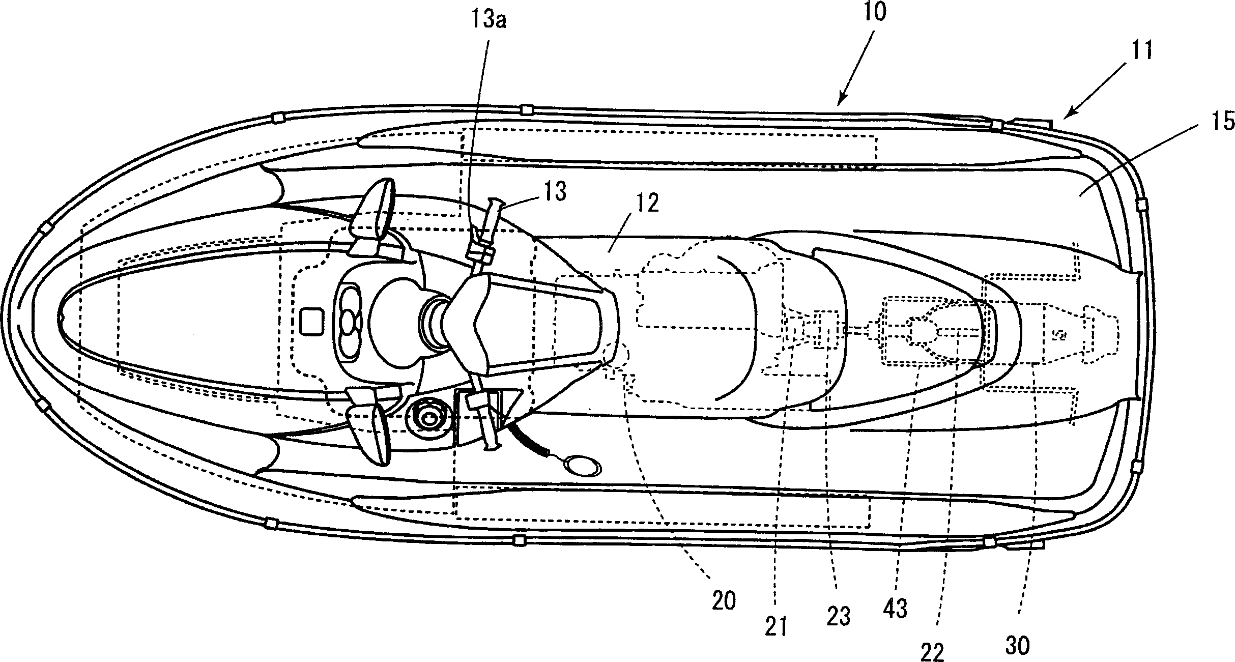
[0053] figure 1 A partially cutaway schematic side view showing an example of a small planing boat using the first embodiment of the bearing structure of the drive shaft for ships of the present invention, figure 2 Show the floor plan for it.

[0054] As shown in these figures (mainly figure 1 ) as shown, this small planing boat 10 is a saddle type small ship, and the occupant sits on the seat 12 of the hull 11 and can hold the steering handle 13 with the throttle lever to operate.

[0055] The hull 11 is of a buoyant structure joining a hull 14 and a deck 15 to form a space 16 inside. An engine 20 is mounted on the casing 14 in the space 16 , and a jet pump (jet propulsion pump) 30 as a propulsion device driven by the engine 20 is provided at the rear of the casing 14 .

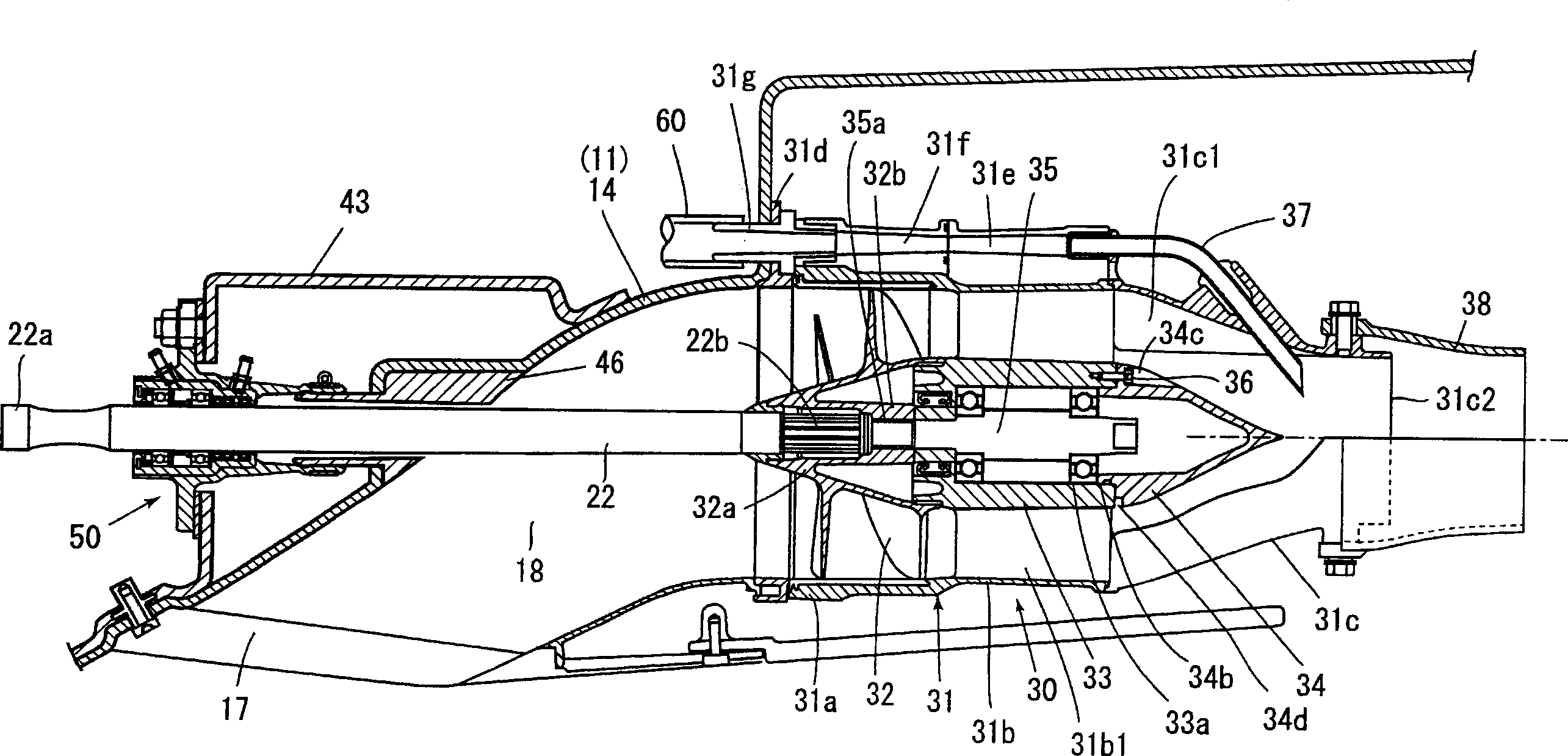
[0056] Jet pump 30 (refer to image 3 ) has an impeller 32 disposed ...


PUM


Abstract

A bearing body for rotatably supporting a drive shaft for driving an impeller on a watercraft body includes a bearing chamber containing bearing members rotatably supporting the drive shaft. Seal members are disposed on both sides of the bearing members and partition the bearing chamber by making contact with an outside circumferential surface of the drive shaft. The seal members are disposed so that grease in the bearing chamber does not leak out through the contact portions between the seal members and the outside circumferential surface of the drive shaft, and a breather passage is communicated with the bearing chamber. Two bearing members within the bearing chamber have a space formed between the bearing members, e.g., to form a grease reservoir between the bearing members. The aforementioned bearing structure reduces the necessity of maintenance, e.g., supplying grease to a drive shaft bearing portion, or at least the reduces the required frequency of maintenance.

Description

technical field [0001] The present invention relates to a bearing structure of a drive shaft for a ship. Background technique [0002] As a bearing structure of a conventional drive shaft for a ship, there are known Figure 7 This is the case shown (Japanese Patent Application Laid-Open No. 7-112697). [0003] In the figure, symbol 1 is the drive shaft, at its front end, the driven side coupling 2 connected with the driving side coupling of the engine not shown in the figure is fixed, and the impeller not shown in the figure is fixed at the rear end, Power is transmitted from the engine to the impeller, which drives the impeller to rotate. [0004] This bearing structure has a bearing body 4 that rotatably supports the drive shaft 1 relative to the hull 3 . [0005] The bearing body 4 has a bearing member (a ball bearing shown in the figure) 5 for rotatably supporting the drive shaft 1, a bearing chamber 6 for accommodating the bearing member 5, and is arranged on both sid...

Claims


Application Information

Patent Timeline
Patent Type & Authority Applications(China)
IPC IPC(8): B63H11/08B63B35/73B63H23/32B63H23/36F02B61/04F16C33/66F16C33/76F16C33/78F16N21/04
CPCB63H23/321F16C33/76F16C33/6622F02B61/045F16C33/6607B63B35/731B63H11/08B63B34/10F16C2326/30
Inventor 布施知洋土谷政彦
Owner HONDA MOTOR CO LTD
Learn More