
Heat dissipating module of notebook computer

A notebook computer and heat dissipation module technology, applied in computing, instruments, electrical digital data processing, etc., can solve the problems of increasing the frictional resistance between the air and the fin 130, increasing the volume of the heat dissipation module, reducing the heat dissipation efficiency, etc., and achieving the difficult boundary effect , Improve heat dissipation efficiency, increase the effect of fin length

Inactive Publication Date: 2003-04-16
WISTRON CORP
View PDF0 Cites 5 Cited by
  • Summary
  • Abstract
  • Description
  • Claims
  • Application Information

AI Technical Summary

Problems solved by technology

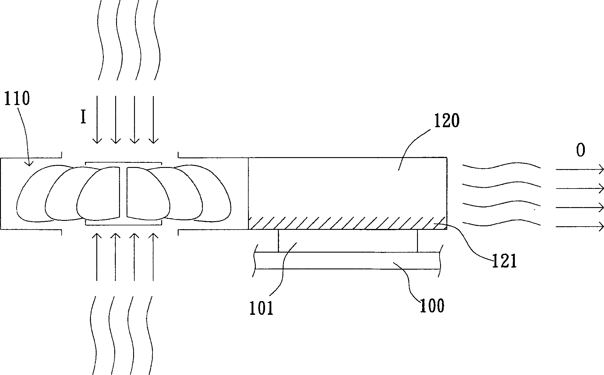
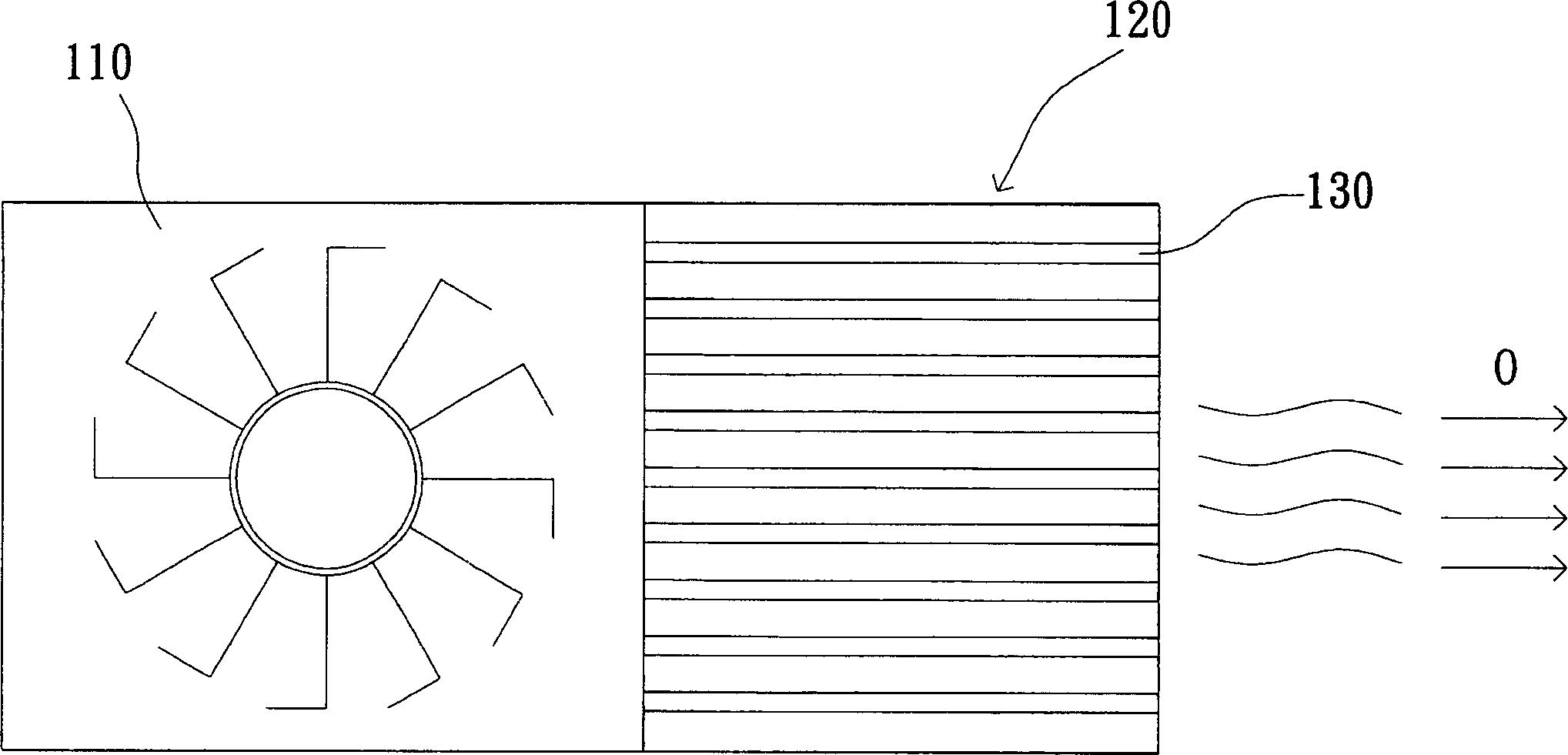
However, increasing the number of fins 130 may cause unsmooth air flow, resulting in noise or wind-cutting sound; increasing the length of the fins 130 will increase the volume of the heat dissipation module, and increase the resistance of the friction between the air and the fins 130, Increase the speed of the fan 110 or cause a boundary effect of heat dissipation, which reduces the efficiency of heat dissipation
If you want to increase the air volume or air pressure of the fan 110, you must increase the power and size of the fan 110, but this conflicts with the light, thin, short, and small characteristics of the notebook computer, so the above methods all have many shortcomings. overcome

Method used


Image

  • Heat dissipating module of notebook computer
  • Heat dissipating module of notebook computer
  • Heat dissipating module of notebook computer

Examples


Embodiment 1

[0020] Then please refer to image 3 , which shows a top view of the heat dissipation module proposed according to Embodiment 1 of the present invention. As shown in the figure, the cooling module includes an inner fan 310 and two radiators 321, 322, and the radiators 321, 322 are connected by a heat pipe 340, and the heat pipe 340 is used as a heat conducting structure of the cooling module. The bottom surface of the heat sink 321 forms a contact surface (not shown) for contacting with the central processing unit 101 (or other types of chips) and exchanging heat; the fan 310 is configured in the notebook computer, and is different from a traditional fan in that There are two air outlets, and the radiators 321 and 322 are respectively arranged at the two air outlets of the fan 310 and coupled with the heat pipe 340 . Many fins 330 are arranged on the radiators 321 and 322 to allow air to pass through, and the fins 330 exchange heat with the passing air to dissipate the heat. ...

Embodiment 2

[0024] Next, please refer to FIG. 4 , which shows a top view of the heat dissipation module provided according to Embodiment 2 of the present invention. As shown in the figure, the cooling module includes a fan 410 and three radiators 421, 422, 423, and the radiators 421, 422, 423 are connected by a heat pipe 440, and the heat pipe 440 is used as a heat conducting structure of the cooling module. The bottom surface of the heat sink 421 forms a contact surface (not shown) for contacting with the central processing unit 101 (or other types of chips) and exchanging heat; the fan 410 is configured in the notebook computer, and is different from a traditional fan in that There are three air outlets, and the radiators 421 , 422 , 423 are respectively arranged at the three air outlets of the fan 410 and coupled with the heat pipe 440 . Many fins 430 are arranged on the radiators 421, 422, 423 to allow air to pass through, and the fins 430 exchange heat with the passing air to dissipa...


PUM


Abstract

The heat emission module of the notebook computer is utilzied to lower the surface temperature of the chips inside the notebook computers. The heat emission module includes following parts. The fan is installed inside computer, including the first and second wind outlets. The air sucked by the fan is discharged through the first and second wind outlets. The first radiator is set at the first outlet, the bottom of the first radiator is contact with the chips for carrying out the heat exchange. The second radiator is set at the second outlet. The heat conducting structure is connected to the first radiator and the second radiator in parallel and utilized to transfer the heat from the first radiator to the second radiator.

Description

technical field [0001] The invention relates to a heat dissipation module of a notebook computer, in particular to a heat dissipation module which utilizes a plurality of air outlets to increase air volume and air pressure to improve heat dissipation efficiency. Background technique [0002] With the development of electronic industry technology, the transistor density of various chips (especially the central processing unit) is increasing day by day. Although the speed of data processing is getting faster and faster, the power consumption and heat generation are also increasing. In order for the central processing unit to operate stably, a high-efficiency radiator has become an inevitable requirement. In order to maintain a high-efficiency heat dissipation function, the volume and weight of the radiator have to be larger and heavier. However, in the design of notebook computers, the limited space has always been the biggest bottleneck in the design. ...

Claims


Application Information

Patent Timeline
Patent Type & Authority Applications(China)
IPC IPC(8): G06F1/20H01L23/36
Inventor 陈明智陈建安
Owner WISTRON CORP
Learn More