Wall element and its manufacturing method

A wall and on-site manufacturing technology, applied in the direction of walls, building components, building structures, etc., can solve the problems of production, transportation and installation plus difficulties, and achieve the effect of simple operation, great flexibility and low cost

Inactive Publication Date: 2003-04-23
JAMES HARDIE INT FINANCE BV
View PDF0 Cites 10 Cited by
  • Summary
  • Abstract
  • Description
  • Claims
  • Application Information

AI Technical Summary

Problems solved by technology

Another drawback is all the added difficulties associated with the aforementioned heavy material production, transport and installation

Method used


Image

  • Wall element and its manufacturing method
  • Wall element and its manufacturing method
  • Wall element and its manufacturing method

Examples


Embodiment Construction

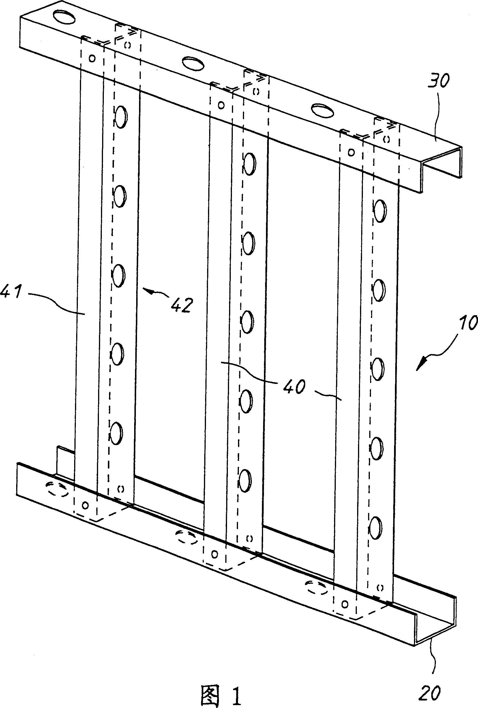
[0033] Referring first to Figure 1, the first step in the method of the present invention is to provide a frame for the desired wall, floor or ceiling. The frame 10 is preferably constructed of a common thin-walled load-bearing steel framework. In this example, the frame 10 includes a lower rail 20 , an upper rail 30 coupled by substantially vertically oriented, spaced apart studs 40 .

[0034] Preferably, the minimum thickness of the material of each frame member is 0.55mm. In the illustrated embodiment, each frame member comprises an elongated "C" section channel member. Other sections, such as "Z" and "I" shapes, are also applicable. Preferably, each frame member includes a pair of spaced apart parallel flanges 41,42. These flanges are not only used to help secure the FRC panels, as described below, they will also reinforce the wall, floor or ceiling.

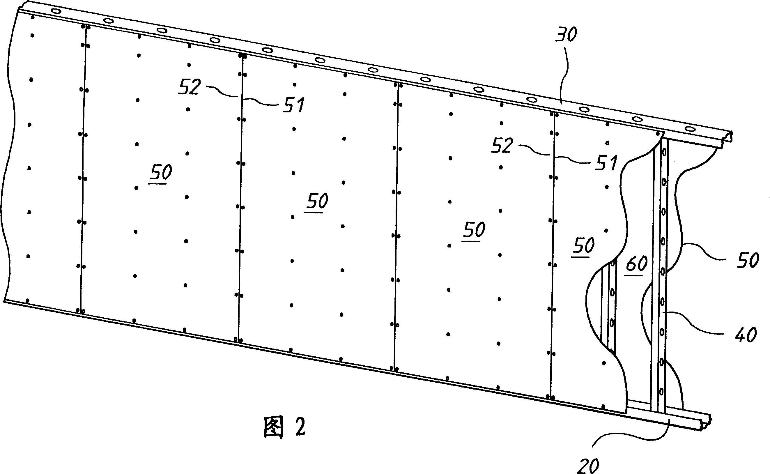
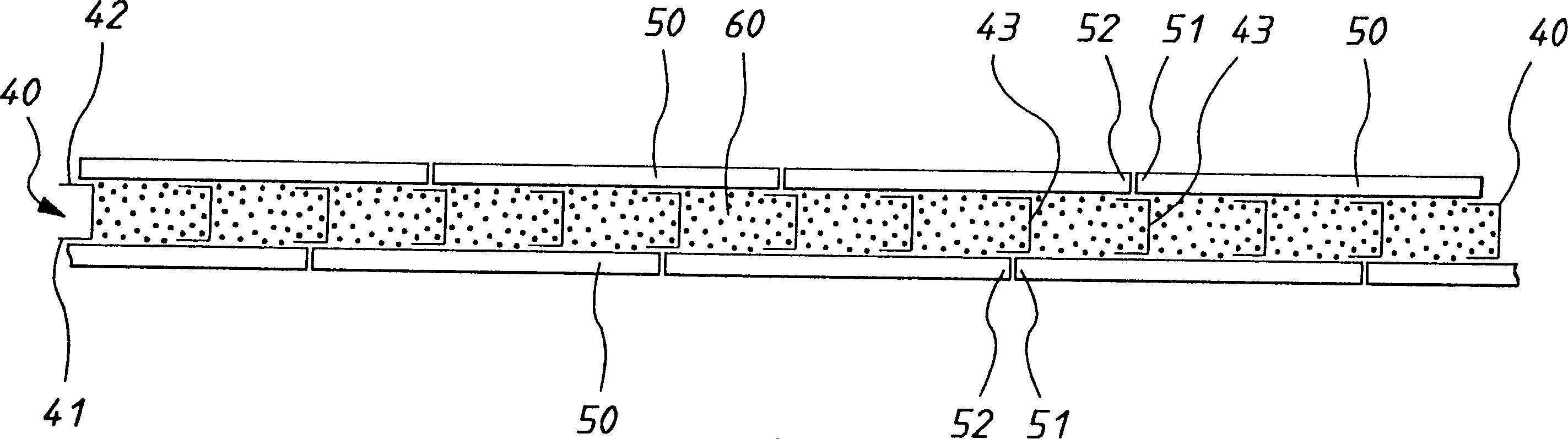
[0035] As shown in Figure 2, the next step in the method of the present invention is to fix a number of fiber cement s...


PUM


Abstract

A process for constructing a wall, floor or ceiling in situ. The process includes the steps of erecting a substantially rigid frame (10) and attaching fiber reinforced cementitious sheets (50) to the front and rear faces of the frame to form a void (60) therebetween. This void (60) is then filled with a lightweight aggregate concrete slurry and allowed to cure. The sheets are adapted to absorb sufficient moisture from the lightweight aggregate slurry to provide natural adherence of the concrete slurry to the sheets without substantially losing their structural integrity during setting and curing of the concrete slurry. Further, The invention provides a wall produced by the same process.

Description

technical field [0001] The present invention relates to an improved wall, floor or ceiling and a method for its manufacture. Background technique [0002] There is a great demand in the construction industry for modern lightweight monolithic wall solutions, with their more attractive prices and greater design flexibility, as an alternative to traditional brick or prefabricated concrete block walls. There is also an urgent need to reduce the construction time of traditional wall building methods. [0003] There are a number of similar-looking, light-duty stucco or "rendered" masonry methods; these employ a common stud frame, sheathed in sheet material and plastered or painted to achieve the masonry appearance. However, while these methods provide the appearance of masonry; however, none of them achieve the "feel" or overall performance of masonry. [0004] Currently, there are many ways of masonry siding available. Typically, such panels are made by injecting a lightweight...

Claims


Application Information

Patent Timeline
Patent Type & Authority Applications(China)
IPC IPC(8): E04B1/16E04B2/72E04B2/86E04B5/29E04B5/36E04C3/04E04C3/07
CPCE04B2/8647E04C2003/0434E04C3/065E04C2003/0421E04B5/29E04B5/36E04C3/07E04C2003/0473E04B1/16E04B2/72
Inventor 约翰·S·科捷戴维·R·柯林斯詹姆斯·G·吉维斯
Owner JAMES HARDIE INT FINANCE BV
Why Eureka
Try Eureka