Optical data processing unit

A technology of optical data and processing devices, applied in the direction of beam guiding devices, optics, optical components, etc., can solve problems such as unproposed, unacceptable, large spherical aberrations, etc.

Inactive Publication Date: 2003-04-30
PANASONIC CORP
View PDF0 Cites 4 Cited by
  • Summary
  • Abstract
  • Description
  • Claims
  • Application Information

AI Technical Summary

Problems solved by technology

However, since spherical aberration is proportional to the fourth power of NA, setups mounted with high NA objectives suffer from unacceptably large spherical aberration
In the past, no easy and accurate method for detecting spherical aberration caused by substrate thickness errors has been proposed

Method used


Image

  • Optical data processing unit
  • Optical data processing unit
  • Optical data processing unit

Examples


Embodiment Construction

[0033] Preferred embodiments of the present invention are described below with reference to the accompanying drawings.

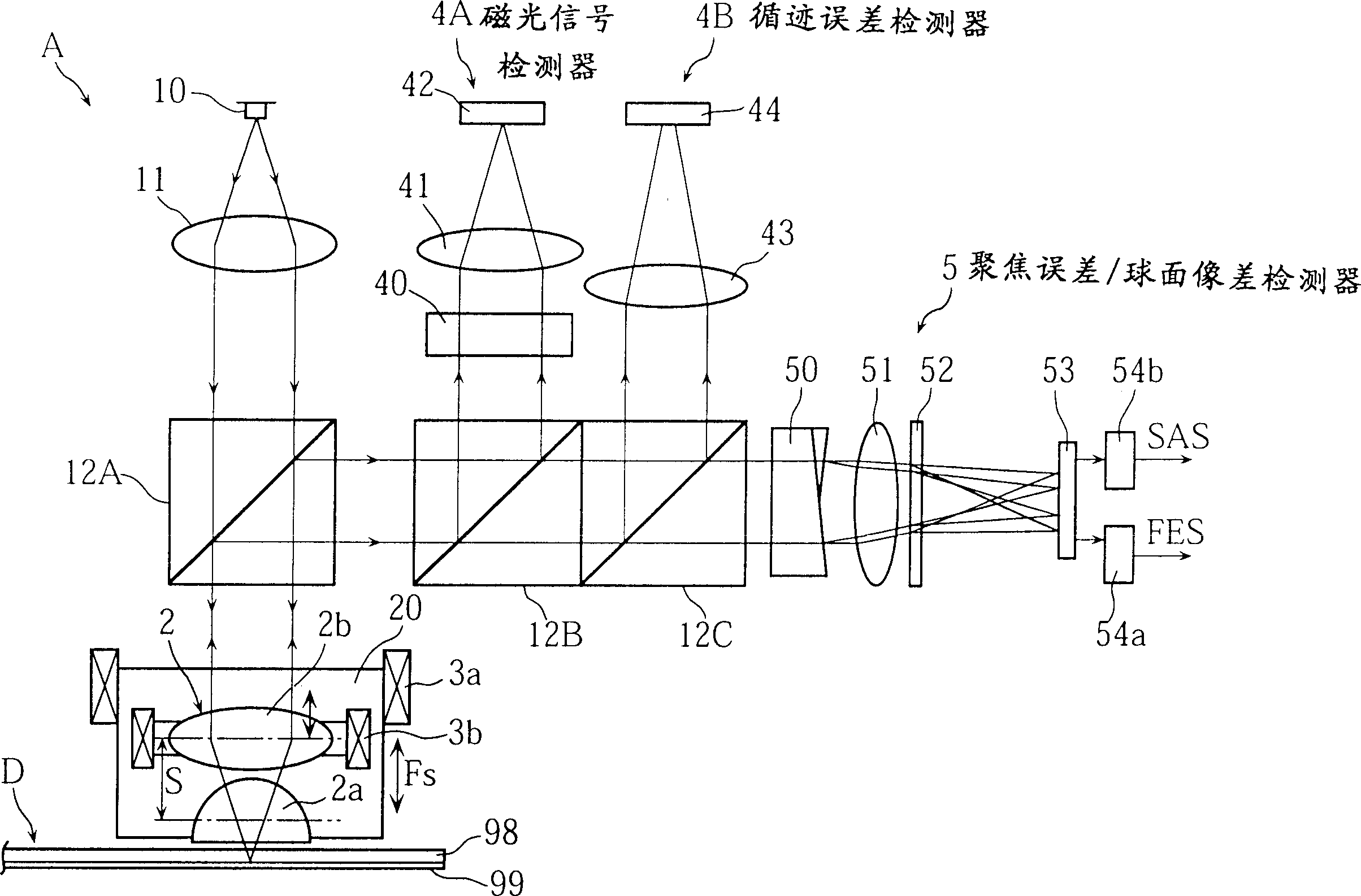
[0034] first reference Figure 1~4 , Figure 1~4 shows an optical data processing apparatus according to a first embodiment of the present invention. as from figure 1Apparatus A is shown as an optical disc apparatus for writing data to or reading data from an optical disc D as seen in FIG. The apparatus A includes a laser diode 10 as a light source, which emits a laser beam to irradiate the optical disc D. As shown in FIG. The emitted light passes through the collimator lens 11 , the first beam splitter 12A and the objective lens assembly 2 . The lens assembly 2 includes a lower lens 2a and an upper lens 2b, the distance between the upper lens 2b and the optical disk D is greater than the distance between the lower lens 2a and the optical disk D. The two lenses are supported by the lens holder 20 . By using more than one lens, a higher NA can be obtai...


PUM


Abstract

An optical data-processing apparatus is provided for writing data to a data storage disk or reading data from the disk. The data-processing apparatus includes first and second light splitters. The first splitter splits reflected light from the storage disk into two semicircular rays. The second splitter splits these two semicircular rays into non-biased light and biased light. The data-processing apparatus also includes an optical detector for receiving the non-biased light and the biased light, thereby producing a first signal corresponding to the non-biased light and a second signal corresponding to the biased light. Based on the first and the second signals, a focus error signal and a spherical aberration signal are produced.

Description

technical field [0001] The invention relates to an optical data processing device of the type provided with an objective lens facing an optical data storage medium in order to generate a light spot on the storage medium. In particular, the present invention relates to a technique for correctly detecting spherical aberration due to thickness error of a storage medium substrate in such a data processing device. In this specification, "optical data storage disc" refers to any type of data storage medium in which desired information can be written and read optically. For example, the optical storage medium may be an optical disc read only (eg CD-ROM), a magneto optical disc or a phase change optical disc. Background technique [0002] Focus errors in optical data devices are usually checked using the Foucault method. The above method can be used in a conventional optical data processing device shown in FIG. 11 . [0003] Specifically, in a conventional device, a laser beam em...

Claims


Application Information

Patent Timeline
Patent Type & Authority Applications(China)
IPC IPC(8): G02B7/28G11B7/00G11B7/09G11B7/125G11B7/13G11B7/131G11B7/135G11B7/1372G11B7/1374G11B7/1381G11B7/1392G11B11/105
CPCG11B7/0948G11B7/1374G11B7/1381G11B7/0916G11B7/13927G11B2007/13727G11B7/131G11B7/00G11B7/09
Inventor 只木恭子
Owner PANASONIC CORP
Why Eureka
Try Eureka