
Positioning and clamping method for processing piston and processing technique

A piston and positioning surface technology, applied in the field of engine pistons, can solve problems such as unstable shape and position tolerances, engine power reduction, cylinder scuffing accidents, etc., to improve product quality and productivity, eliminate coaxiality errors, and shape and position tolerances stable effect

Inactive Publication Date: 2003-05-07
薛玉田
View PDF0 Cites 16 Cited by
  • Summary
  • Abstract
  • Description
  • Claims
  • Application Information

AI Technical Summary

Problems solved by technology

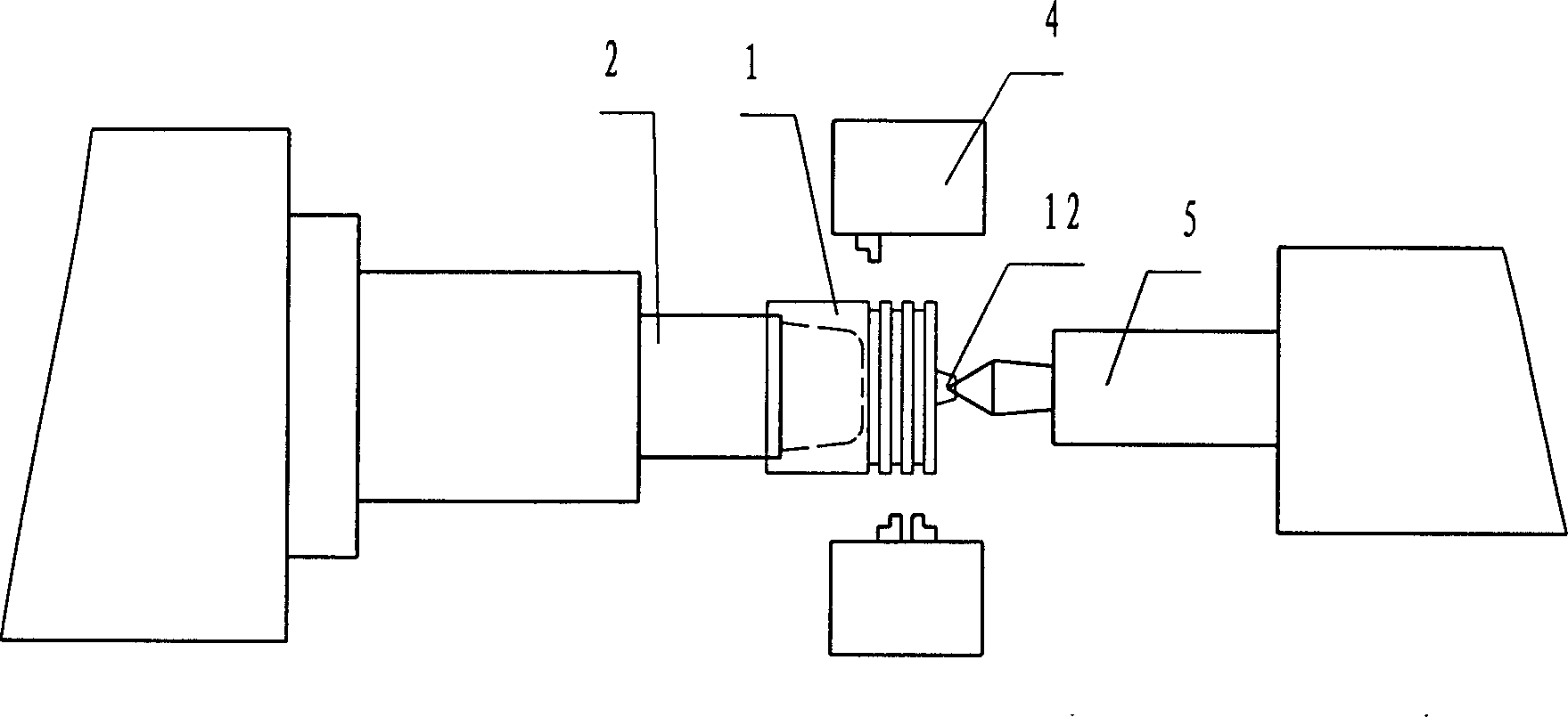
[0002] The piston has three important processing surfaces, the outer diameter of the piston, the inner diameter of the pin hole, the width and depth of the ring groove, such as figure 1 As shown, the existing clamping method for piston processing is based on the positioning of the inner diameter seam of the piston and the positioning of the plane of the inner diameter seam and the pin seat hole. , After the processing is finished, the clamping is loosened, the piston rebounds and deforms, causing the piston to increase the tendency of air leakage during use, reducing the engine power, increasing fuel consumption, and increasing emissions, which will seriously cause cylinder scuffing accidents
Positioning with the inner diameter spigot, the machining chips on the positioning surface are not easy to clean, which will cause the shape and position tolerance of the piston outer diameter, ring groove, and pin hole to be unstable (perpendicularity and parallelism are out of tolerance), directly affecting the normal operation of the piston in the cylinder. Work, increase emissions, and even pull and knock on cylinders

Method used


Image

  • Positioning and clamping method for processing piston and processing technique
  • Positioning and clamping method for processing piston and processing technique
  • Positioning and clamping method for processing piston and processing technique

Examples


Embodiment Construction

[0016] The utility model is described in detail below in conjunction with the drawings

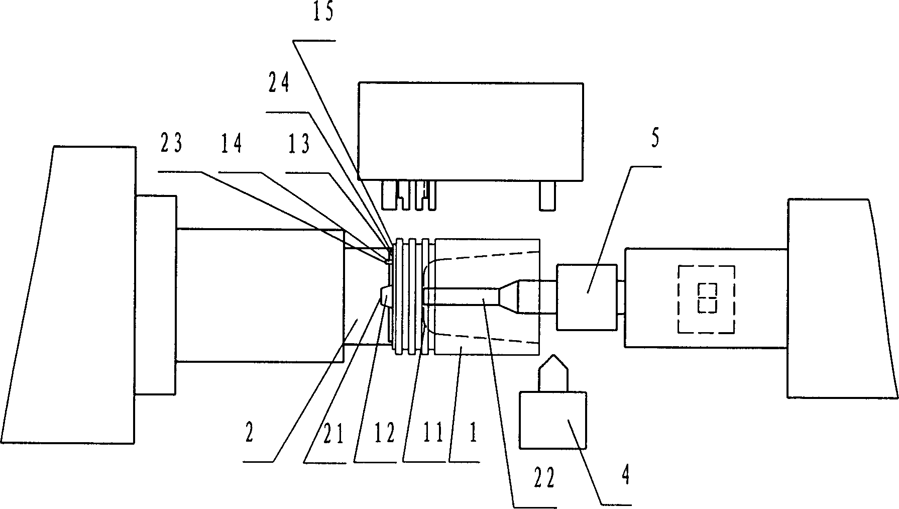
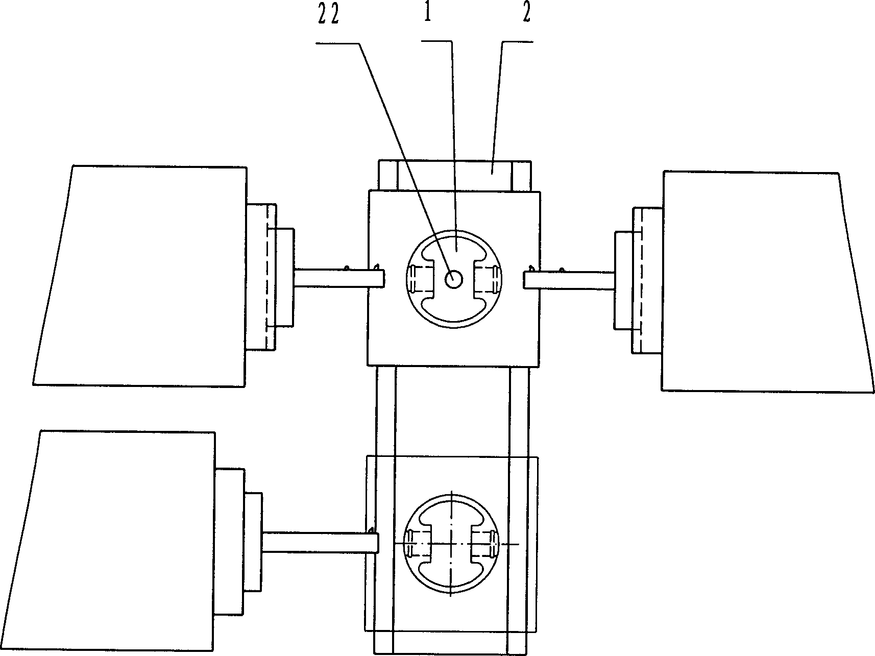
[0017] The positioning and tightening method for piston processing is as follows: 1) provide processing machine tools; 2) provide processing tools and fixtures 2; 3) use the top 11 of the inner cavity of the piston 1 as the clamping point, and use the outer end surface 13 of the top of the piston and the positioning boss 12 is a positioning surface.

[0018] Compared with the previous processing technology, the piston processing technology arranged by the positioning and tightening method of the piston reduces the number of installations. It includes the following steps: 1) providing processing machine tools; 2) providing processing tools and fixtures; 3) using the outer end surface of the top of the piston and the positioning boss as the positioning surface, with the top of the piston inner cavity as the clamping point, the outer diameter of rough turning---rough and finish turning ring g...


PUM


Abstract

A locating and clamping method for machining piston includes providing machine-tool, cutter and fixture, using the top of the inner cavity of the piston to be machined as the point to be clamped, and using the external end face and locating boss of the piston as the locating surface. Its advantages are no deformation caused by clamping, high locating precision, and high productivity and quality.

Description

technical field [0001] The invention belongs to a piston of an engine, in particular to a clamping method and a processing technology for processing the piston. Background technique [0002] The piston has three important processing surfaces, the outer diameter of the piston, the inner diameter of the pin hole, the width and depth of the ring groove, such as figure 1 As shown, the existing clamping method for piston processing is based on the positioning of the inner diameter seam of the piston and the positioning of the plane of the inner diameter seam and the pin seat hole. , After the processing is finished, the clamping is loosened, the piston rebounds and deforms, causing the piston to increase the tendency of air leakage during use, reducing the engine power, increasing fuel consumption, increasing emissions, and serious cylinder scuffing accidents. Positioning with the inner diameter spigot, the machining chips on the positioning surface are not easy to clean, which ...

Claims


Application Information

Patent Timeline
Patent Type & Authority Applications(China)
IPC IPC(8): B23P15/10
Inventor 薛玉田
Owner 薛玉田
Learn More