

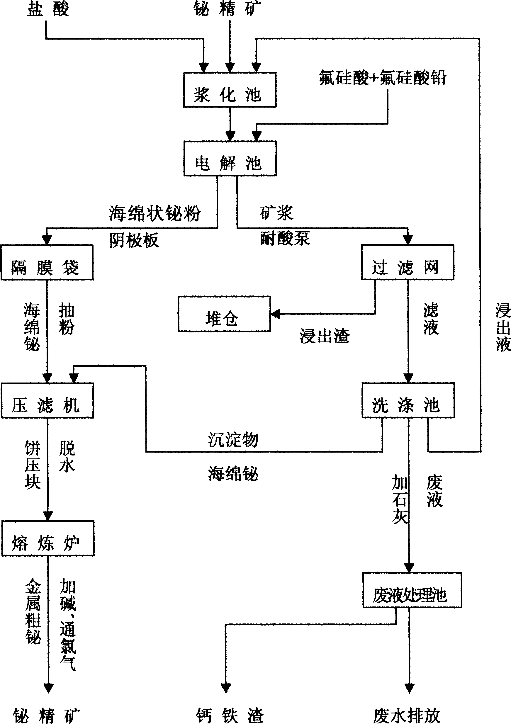
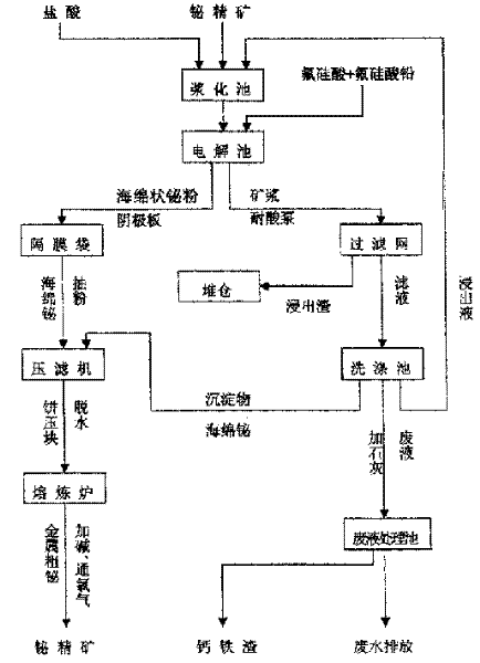
Technique for electrolyzing slurry of fluosilicic acid in bismuth mine
A technology of slurry electrolysis and fluorosilicic acid is applied in the refining field of bismuth, which can solve the problems of low efficiency and complicated operation, and achieve the effects of simplified equipment structure, simple process, and reduced cost and energy consumption.
- Summary
- Abstract
- Description
- Claims
- Application Information
AI Technical Summary
Problems solved by technology
Method used
Image

Examples
Embodiment Construction
[0030] The following embodiments will further describe the present invention in detail:
[0031] This implementation mode takes Xujiadong Fengrun Smelter as an example. The total construction area of the production plant and power supply room of the project is 1000m 2 , the power supply is a 500KVA transformer.
[0032] The main equipment used in this embodiment is selected as:
[0033] 1. Pulp electrolytic slurry tank
[0034] Select Φ1500×2000mm (V 液 =3.5m 3 ) Two pulping tanks, motor power 2.2kw×2=4.4kw, made of acid-resistant steel bricks.
[0035] 2. Slurry electrolyzer
[0036] The size of the slurry electrolytic cell is 2000×1500×1750mm, the DC current intensity is 2700A, and the electrolysis time is 1.25 times of the theoretical electrolysis time of bismuth, so the daily concentrate volume of a single tank is 2700×2.6÷100×22÷1.25÷20%=618kg / d tank; number of pulp electrolyzers: 7.41×2252÷618=18, divided into three rows, each row with 9 electrolyzers connected i...
PUM
 Abstract
Description
Claims
Application Information