Compressor

A compressor and pressure plate technology, applied in the field of fluid compressors, can solve the problems of complex structure, large compressor volume, and large radial size protrusion.

Inactive Publication Date: 2003-05-07
DENSO CORP
View PDF4 Cites 6 Cited by
  • Summary
  • Abstract
  • Description
  • Claims
  • Application Information

AI Technical Summary

Problems solved by technology

The first reason is that it is desired to install the capacity control valve 33 inside the compressor, but there is no space inside the compressor to accommodate the capacity control valve 33
The second reason is that the capacity control valve 33 accommodates both the low-pressure fluid of the suction chamber 31 and the high-pressure fluid of the discharge chamber 32 to generate any pressure between those high and low pressures, which is supplied to the driving disc chamber 1a, and therefore, if When the capacity control valve 33 is installed on the rear frame 3 provided with the suction chamber 31 and the discharge chamber 32, the connecting flow path becomes short an

Method used


Image

  • Compressor
  • Compressor
  • Compressor

Examples


Embodiment 1

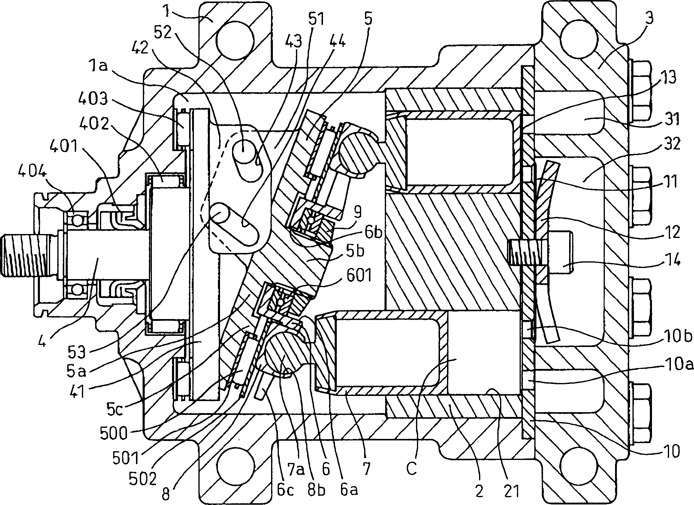
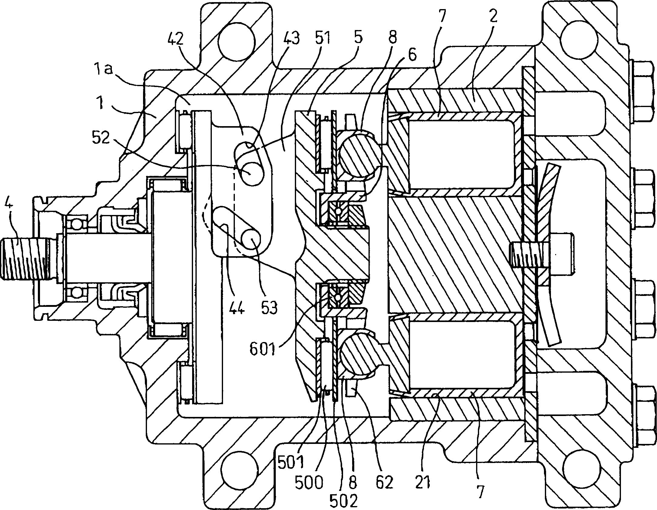
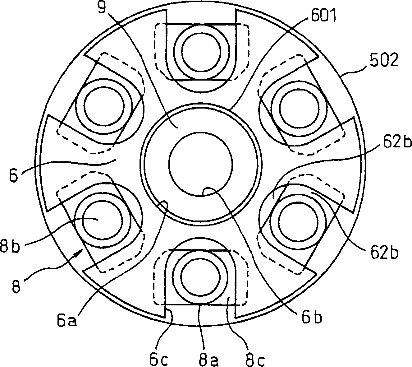
[0100] The specific shape of the tile support plate 6 of embodiment 1, if referring to figure 1 , figure 2 and image 3 It's clear. The shoe support plate 6 has a concave surface 6a at the center, and a shoe support plate thrust bearing 601 can be installed in the concave surface 6a. As described above, the center hole 6b for mounting the hub 5b of the drive disk 5 is formed at the center portion of the concave surface 6a. There are radial U-shaped notches with the same number (for example, 6) as the number of pistons 7 on the edge of the tile holding plate 6 as guide grooves 6c.

[0101] There is a sliding fit in the guide groove 6c image 3 and Figure 4The shoe main body 8a of the friction-resistant shoe 8 having the shape shown is approximately a cylindrical shape with a bottom. The tile support plate 6 and the drive disc 5 can be matched in relative rotation, and the shoe support main body 8a installed in the guide groove 6c of the tile support plate 6 is matched w...

Embodiment 7

[0132] The variable capacity compressor of Embodiment 7 has a torsion coil spring 15 acting in this way, so in Figure 12 The indicated stop of operation or Figure 11 When the discharge capacity shown is zero or the minimum operating state, the force FB2 is generated to increase the inclination angle of the drive disk 5, so the operation stops without the back pressure FH acting in the front frame chamber 1a of the piston 7 state or when the operation starts with little back pressure FH, the driving disk 5 is forced to take a given inclination angle due to the force FB2, and becomes Figure 12 status shown. in addition, Figure 11 As shown, when the discharge capacity is zero or minimum during operation, the internal pressure FH of the front frame chamber 1a is high, and the compression reaction force FP of the working chamber C is small. Even if the force FB2 of the torsion coil spring 15 exists, the drive The inclination angle of the disk 5 becomes zero or minimum. Ther...

Embodiment 14

[0153] The variable capacity compressor of Embodiment 14 has high-speed sliding between the shoe supports 19, 20 and the drive disc 5, so it is not suitable for high-speed, high-load operation, but except for the space between the drive disc 5 and the shoe 8 Except for cooperation, the structure of other parts is the same as that of Embodiment 1, so the drive disc 5 is matched on one side by the drive shaft 4 utilizing a cantilever beam form of a double sliding link mechanism, and the same actual effect of Embodiment 1 can be obtained. Therefore, Embodiment 14 is an example in which the technical idea of ​​the present invention can be applied to a variable capacity compressor using the conventional shoes 19 and 20 .

[0154] In Embodiment 14, as a detailed structure, the arm 51 for driving the disk 5 and the Figure 10 The shown embodiment 7 is the same, and in embodiment 14, it is divided into an upper arm 51a and a lower arm 51b, such as Figure 31 shown, and consists of a ...


PUM


Abstract

A piston type compressor having a drive plate (swash plate), wherein sliding friction between the drive plate and shoes is reduced and the compressor is made smaller by slidably attaching the shoes engaged with spherical ends of pistons to a shoe holding plate formed with guide grooves in the radial direction and supporting the shoe holding plate by the drive plate through a thrust bearing. The drive plate is connected to an arm of the shaft side through a double slide link mechanism to enable it to be supported by only a front end of the front housing.

Description

technical field [0001] The present invention relates to fluid compressors such as refrigerant compressors used in refrigeration cycles of air conditioners mounted on vehicles, for example. Background technique [0002] There are two representative forms of conventional drive disk piston (or swash plate) compressors. One form is that it is installed on the front and back sides of the drive disc that rotates and swings on the drive shaft relative to the tilted state, and the two hemispherical shoes installed at the end of the piston rod are in direct frictional contact, so that the piston directly For reciprocating motion. The problem with this type of compressor is that when the compressor rotates at high speed, the relative sliding speed between the drive disc and the shoe is high, and the lubrication state between the drive disc and the shoe is not good under the operating condition of insufficient lubricating oil supply. , prone to poor adhesion. In addition, since the ...

Claims


Application Information

Patent Timeline
IPC IPC(8): F04B27/08F04B27/10
CPCF04B27/1063F04B27/1054F04B27/0882F04B27/0878F04B27/1072
Inventor 神谷裕一神谷茂井上雅文井上孝松田三起夫
Owner DENSO CORP
Why Eureka
Try Eureka