
Electric actuator and fixing structure of actuator

An actuator and electric technology, applied in the direction of electric components, electromechanical devices, electrical components, etc., can solve the problems of not being able to maintain a fully closed state, bolt hole processing time-consuming, complex and large-scale structures, etc., to achieve excellent safety and man-hours less, the effect of preventing danger

Inactive Publication Date: 2003-05-07
KITZ CORP
View PDF3 Cites 8 Cited by
  • Summary
  • Abstract
  • Description
  • Claims
  • Application Information

AI Technical Summary

Problems solved by technology

[0005] However, the structure of the conventional manual operation mechanism of the electric actuator tends to be complicated, the overall shape tends to be large, and the operability during manual operation is poor. In particular, tools are usually used for manual operation. Therefore, it is expected to develop solutions to these problems. Subject's Electric Actuator
In addition, when attaching or detaching such an actuator to a valve, the bolt hole for inserting the mounting bolt provided on the flange of the valve or the actuator is formed in consideration of the fitting tolerance between the bolt and the bolt. The hole slightly larger than the outer diameter of the bolt, if the bolt is loose, the actuator may be misaligned in the gap between the bolt hole and the bolt, so the fully closed state cannot be reliably maintained when the rotary valve is fully closed, etc. There is a possibility of impairing the function of the valve
In addition, when bolt holes are formed on the flange, not only is it labor-intensive to process the bolt holes, but also space for loosening the bolts by rotating them is required when the actuator is attached or removed, and a wrench and a screwdriver are also required. other working tools

Method used


Image

  • Electric actuator and fixing structure of actuator
  • Electric actuator and fixing structure of actuator
  • Electric actuator and fixing structure of actuator

Examples


Embodiment Construction

[0072] In order to explain this invention in more detail, it demonstrates using drawing.

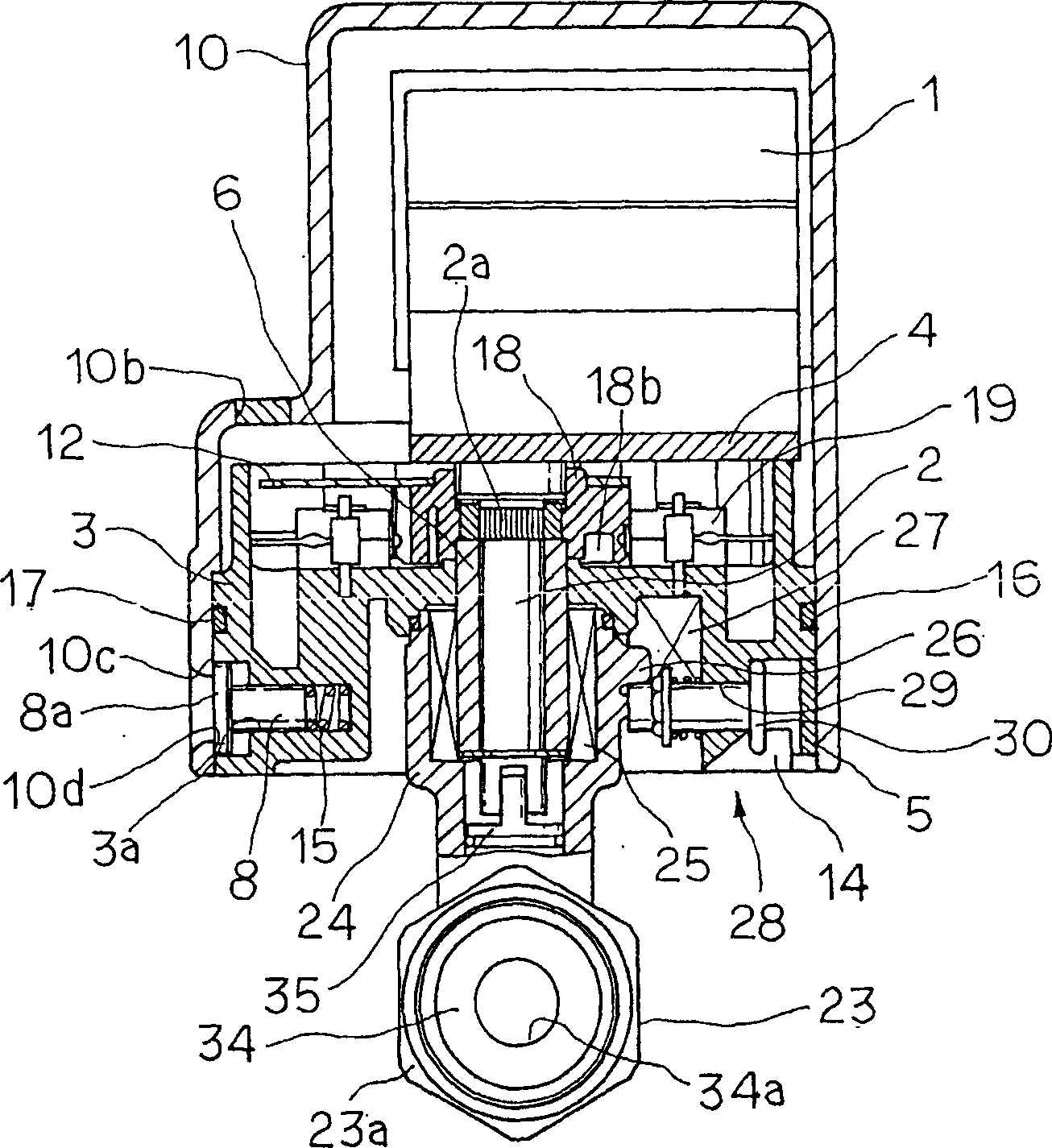
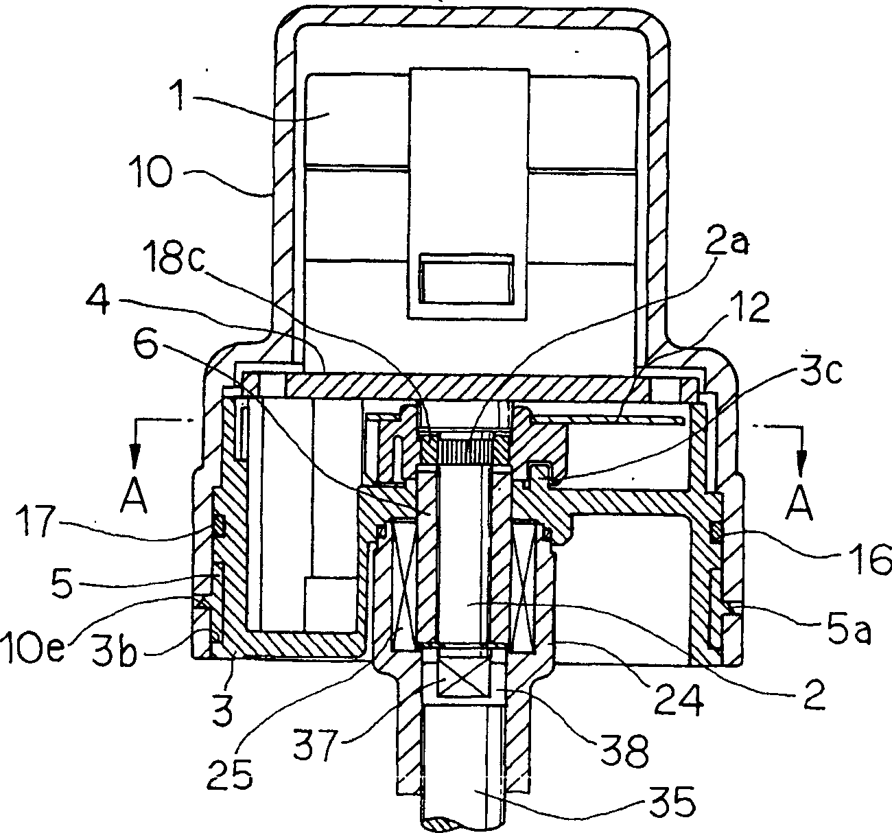
[0073] An example of the electric actuator in the present invention applicable to a rotary valve such as a ball valve will be described with reference to the drawings. figure 1 In the present invention, the drive shaft of the motor 1 is pivotably mounted on a disc-shaped base 3 in a freely rotatable manner. The motor 1 uses a geared motor incorporating a reduction gear with a high gear ratio. This geared motor has a self-locking function of the drive shaft 2 when it is not energized. In this case, the drive shaft 2 rotates integrally with the motor 1. .

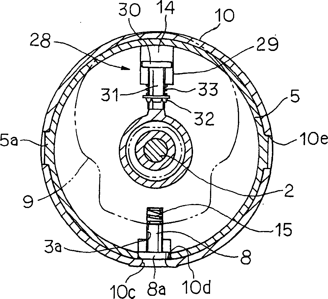
[0074] Also have, cover body 10 such as Figure 12 As shown, it has a combined curved surface 9 that is easy to hold on the outside, for example, it is in the shape of a manual gas cock, and is a container-shaped cover body integrally molded with synthetic resin. The cap body 10 can be manually operated within a predetermined range o...


PUM


Abstract

The structure of an electric actuator is simplified to provide a compact, lightweight, inexpensive, safe electric actuator and to obtain an electric actuator that is attachable to and detachable from a rotary valve with one stroke and obtain a fixing structure for the electric actuator. There is also provided a fixing structure for a pair of constituent members, such as machine parts, that can particularly fix an electric actuator and a rotary valve to each other with exactitude while restraining the two from moving in their rotating and axial directions and that is compact and enables easy and secure fixation. In an electric actuator having inner component parts thereof inclusive of a motor 1 coated with a cover main body 10, the cover main body 10 having a coating function serves as a manually operating part and is equipped with a mechanism for switching between electrical and manual operations. A fixing structure for connecting and fixing an electric actuator 40 and a rotary valve 23 includes an annular one-way clutch structure 25 disposed at one of opposite fixing positions and an annular face part 6 disposed at the other of the opposite fixing positions. The annular face part 6 is inserted into the one-way clutch structure 25, thereby restraining the actuator and valve from being rotated in one circumferential direction.

Description

technical field [0001] The present invention relates to an electric actuator mounted on a rotary valve such as a ball valve, a butterfly valve, and a fixing structure of the electric actuator that enables detachment between the rotary valve and the actuator by one touch. Configurations can also be applied to fixed configurations of mechanical parts. Background technique [0002] Usually, this kind of actuator connects the drive shaft of the motor provided inside the actuator to the valve stem of the valve or through a clutch mechanism or directly connects the two to automatically open and close the valve. However, in the case of a power failure or an emergency, it is necessary to manually switch the valve. [0003] Here, the conventional method is to install a manual operation shaft on the above-mentioned clutch mechanism or separately, or make the drive shaft of the motor protrude from the upper or lower part of the cover, and use a tool to manually operate the protrusion,...

Claims


Application Information

Patent Timeline
Patent Type & Authority Applications(China)
IPC IPC(8): F16K31/04F16K31/05H02K7/108H02K7/116H02K7/118H02K7/14H02K11/00
CPCF16K31/05H02K7/102H02K7/14Y10T137/1782H02K7/116H02K11/0015F16K31/041H02K11/21H02K5/04
Inventor 青木和弘
Owner KITZ CORP
Learn More